Purpose
Ship’s stability calculations not only rely on the ship’s geometry but also on the knowledge of where the ship’s centre of gravity (G) is positioned. Although the distance of G from the keel can be ascertained for various conditions that the ship may be in, it is essential that it is accurately known for one specified ship condition.
To this end, the need to carry out an inclining experiment becomes necessary and from this, two facts should become known:
- the displacement; and
- the position of G in a known ship’s condition.
The inclining test is carried out to find the lightship KG at the lightship displacement. It is sometimes known as a ‘controlled list experiment’. By conducting the experiment by means of a series of weight shifts, the GM of the vessel can be ascertained under the test condition. This GM value can then be compared with the ship’s KM to obtain the vessel’s KG value: KM – GM = KG
The environment of the dry dock is ideal for performing such a stability check. While the vessel is in the dock, it is usually in its light condition, the water is still and the facilities for moving known weights are readily on hand.
Conditions for Carrying Out the Inclining Experiment
- The vessel should be upright.
- The moorings should be slack, allowing the vessel to be inclined without restraint.
- The vessel should be in still water conditions.
- The density of the water should be known.
- There should be no free surface action inside the ship’s tanks.
- The contents and weights of all the ship’s compartments should be known.
- Calm weather conditions should prevail.
- The vessel should be clear of all unnecessary personnel.
- The light condition displacement should be known from the builders.
- The fore and aft draughts and the mean draught should be noted.
Experiment Preparations
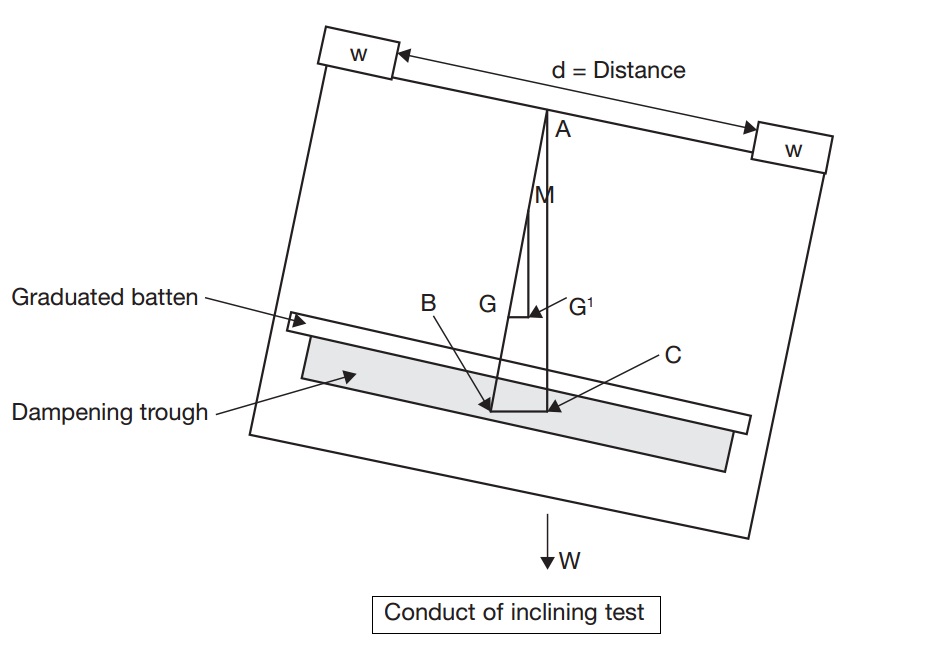
The ship in an upright position, in its light condition, is fitted with a wire plumb line suspended from a high point on the transverse centre line. The ‘plumb bob’ on the end of the line is set into a horizontal trough of light oil or other viscous substance to dampen the movement of the plumb bob, once the vessel is inclined. Fastened to the edge of the trough is a graduated scale batten, measured in millimetres.

Plumb Bob
The inclining weights are then placed on board, preferably by the dockside cranes. These weights are usually fitted with a wheeled platform to assist movement on board the vessel, throughout the period of the experiment. Finally, all non-essential persons are sent ashore and the gangway is landed.
Conduct of the Experiment
The vessel is then caused to be listed over, by moving the weights of the ship’s centre line, to a measured, accurate distance in a horizontal direction.
Because the exact weight and the exact distance are known, a set of listing moments can be obtained.
List Moments + Displacement = GG1 (namely the horizontal shift in the ship’s C of G)
Unless the displacement value is known, it would be usual practice to carry out a draught survey prior to conducting the experiment in order to obtain the exact displacement figure.
Graphic Presentation (vessel floating freely)
- Consider the two similar triangles ABC and GMG1
- In triangle ABC: AB represents the length of the plumb line.
- BC represents the deflection when the ship is heeled.
- In triangle GMG1: GM represents the ship’s metacentric height in this condition.
- GG1 is the shift of ‘G’ due to the moving weight.
As the triangles are similar:
Then Tan Ø = GG1 + GM but Tan Ø = BC ÷ AB
Therefore: GM = GG1 × AB + BC
But GG1 = (w × d ) ÷ Displacement
Therefore: GM = (w × d × AB) ÷ (Displ. × BC)
Where: w × d = list moments (in tonne metres)
AB = Length of the plumb line (in metres)
BC = Deflection of plumb line (in metres)
Displ. (W) = Ship’s weight in this condition
Inclining Test – Example
Question 1.:
A vessel is to undergo an inclining test in the following condition:
Displacement = 9,400 tonnes KM = 8.5 metres
Ballast on board =680 tonnes at a KG of 2.8 metres (FSMs = 166 tm)
Fuel on board =160 tonnes at a KG of 1.4 metres (FSMs = 200 tm)
Freshwater on board =80 tonnes at a KG of 3.0 metres (tank full)
The inclining weight on board = 60 tonnes at a KG of 9.0 metres. The plumb line has a length of 7.6 metres. The weight is shifted 6 metres horizontally and gave a deflection of 850 mm
Calculate the lightship displacement?
Answer.:
GM = (w × d × Plumb line length) ÷ (displacement × deflction)
GM = (60 × 6 7.6) ÷ ( 9400 × 0.85)
GM = 2736 ÷ 7990
GM = 0.3424 m
KG = 8.5 m – 0.3424 = 8.1576 m
Take moments about the keel:
Comm Weight x KG of Distance = Moment
Displ 9400t x KG of 8.1576m = 76681 tm
Ballast – 680 t x KG of 2.8m = – 1904 tm
Fuel – 160 t x KG of 1.4m = – 224 tm
F.W. – 80 t x KG of 3.0m = – 240 tm
Incl Wt – 60 t x KG of 9.0m = – 540 tm
FSMs – 360 tm
8420 t 73407 tm
Lt. Ship KG = 73407 ÷ 8420
KG = 8.7182 metres
[…] 4. The Inclining Experiment – Ascertain the GM of Vessel – Cult of Sea, https://www.cultofsea.com/ship-stability/the-inclining-experiment/ […]