Contents
Cavitation of a ship’s propeller is phenomena that can greatly reduce a ship propelling efficiency whilst at the same time lead to rapid degradation of the propellor.
To learn further about cavitation, we need to get familiar or refresh our knowledge regarding Liquid vapour phases.
- Solid (ice)
- Liquid (water)
- Vapour (steam)
The phases of liquid and vapour are influenced by temperature and pressure. Water is normally observed to change its state to the form of vapour when its temperature is raised to above 100 deg C at atmospheric pressure. Water can also vaporise when the pressure is reduced under normal conditions of temperature. At physical sea temperatures, this requires a pressure less than approximately 1.5 to 2.0 kN/m2.
Cause of Propeller Cavitation
The blades of a propeller develop a total force in a certain direction by virtue of being set at a small angle of ‘incidence’ to the resultant direction of flow of water passing through the propeller.
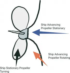
Relative Velocities of the Water
The effect of the flow past the blades is to cause a positive pressure on the face and a reduced pressure or suction on the back due to increased velocities of flow. This increased velocity is due to the shape of the propeller blade section.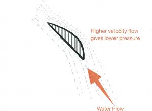
The sum total of these pressure distributions produces the total force whose axial component gives the propeller thrust force. It so happens that under normal working conditions of a ship’s propeller the suction force on the back of the blade represents about 80% of the total force.
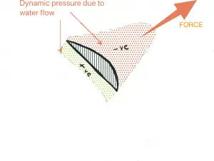
Dynamic Pressure due to water flow
In the working region of the propeller, the net pressure at any point in the water is the algebraic sum of the atmospheric pressure, pressure due to the head of water and the dynamic pressure induced by the working of the propeller.
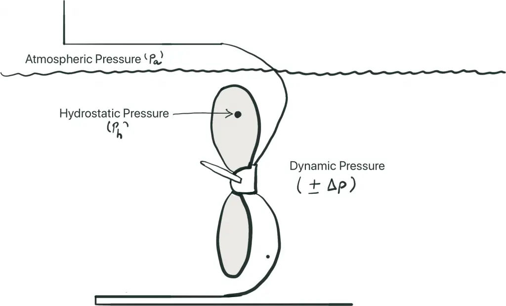
Net Pressure at a Given point
If net pressure reduces to a value below the vapour pressure 9e), then the water will vaporise and cavities will be formed. The creation of these cavities is known as cavitation.
Thus, Cavitation occurs if:
p(a) + p(h) ± Δp < e
This can only occur when Δp is sufficiently negative.
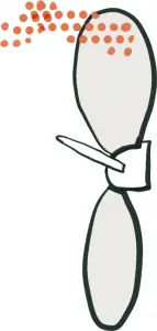
Since cavitation is affected by pressure and temperature, it is more likely to occur in propellers operating near the surface in warm waters.
Thus, if the seawater passing across the back of the blade, meets the suction region and the net pressure of the waterfalls below the vapour pressure of the water at that temperature, cavity bubbles are formed. The cavities expand as the pressure reduces, then contract as the pressure rises and the vapour converts back to liquid.
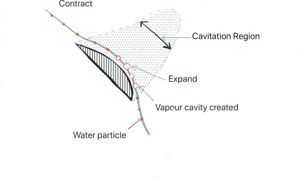
Cavitation Bubbles formation
Types of Cavitation
- ‘Sheet‘ or ‘Laminar‘ cavitation takes the form of a thin stationary sheet usually commencing at the leading edge of the blades.

Sheet or Laminar Cavitation
- In certain conditions, sheet cavitation breaks down behind the blade into a form known as ‘mist‘ or ‘cloud‘ cavitation.
- ‘Bubble‘ cavitation as the name implies, is the formation of distinctive bubble cavities.

Bubble Cavitation
- ‘Vortex‘ cavitation has the appearance of a stranded twisted rope and can be present at either the blade tips or the boss.

Vortex Cavitation
Cavitation increases with the higher loading of the blades, i.e. with larger angles of incidence or with different blade section shapes.
Effects of Cavitation
The effects of cavitation may be listed as :
- Reduced Performance
- Blade Erosion
- Vibration
- Noise
Performance
The effects of cavitation on performance can be considerable. Cavitation usually starts at the blade tips and spread gradually over the entire blades as the propeller loading is increased. When cavitation has extended to about 0.75 of the radius it is found there is a considerable loss in thrust followed by a reduction in torque which means in practice that, there will be a marked increase in revolutions for a given power. Since the thrust breakdown proceeds more rapidly than the change in torque there can be a considerable loss in efficiency.
Erosion
Erosion is a potentially serious effect. The cavitation bubbles, when formed, cannot persist if they are swept into a region where the net pressure returns to a value exceeding the vapour pressure of the water. This may occur towards the trailing edge of the blade or as the blade moves from the top to the bottom of the circle gaining hydrostatic pressure. The manner in which they collapse introduces a new phenomenon, the bubbles contract to a very minute size before they disappear and the whole of the energy of collapse & change of state is therefore concentrated to a very small area. It has been estimated that the final pressure at the point of collapse may exceed 2.3 x 10⁹ N/m². This obviously has a serious effect on the surface of the metal of the blades which can be quickly eroded.
In the initial stages of the attack, the metal takes the appearance of having been struck rapidly with a small ‘peening’ hammer and minute circular indentations are seen on the surface marking the point of collapse of successive bubbles. If the cavitation is more extensive or persists for a longer period of time then it results in serious pitting corrosion of the metal causing a definite crater or series of craters in the surface of the blades, leaving the sponge-like appearance which is characteristics of advanced cavitation erosion.
The tips of the propeller blade and trailing edges are particularly susceptible to erosion and may be completely eroded and torn away by the effects of cavitation. In some instances the continual pitting cause the whole thickness of the blades to be eaten away and finally making a hole through the blade back to face.
Erosion due to cavitation may occur at any part of a propeller blade where the suction is high but in common over three significant regions:
- At the tip where the rotational speed is highest,
- At 0.7 radius where the load is usually at a maximum,
- Towards the root of the blade where the sections are of necessity very thick and the pressure distribution is adversely affected by the small gap between the blades.
Vibration
Vibration is created due to the unsteady nature of the cavitation and is termed as the periodic deflection of the structure in a vertical, horizontal or torsional manner.
Noise
The collapsing cavities give rise to noise effects which, accompanied by high-frequency vibrations, can be extremely unpleasant to passengers and crew if they are situated in the aft end of ship accommodation.
Means of Avoiding Cavitation
- Increase the total blade area and thus the thrust per unit area of blade surface for the same total thrust. This may be accomplished by increasing the blade area ratio at constant diameter or increasing the diameter of the propeller with a resultant reduction in revolutions.
- Reduce the blade angles and angle of incidence by adopting slightly larger diameters.
- Vary the pitch over the length of the blade in order to diminish the loading in critical regions.
- Avoid the occurrence of unduly high sections on the back of the blades by using section shapes which give a more uniform distribution of pressure.
- Design stern to achieve as uniform a wake field as possible.
- Avoid the incidence of local suction peaks near the leading edge by using suitable amounts of camber and a suitable shape of the entrance.
- Reduce the thickness of blades by using materials which are stronger and more resistant to the effects of cavitation.
- Provide the maximum immersion possible.
- Reduce the revolutions per minute. Since the thrust of a propeller varies as the square of the revolutions, then reducing the revolutions will reduce cavitation but will also result in a loss of speed.
A propeller is said to be fully cavitating when the whole of the back is covered in sheet cavitation. This phenomenon is also called super cavitation. After the back of the section has become completely denuded of water, the increase in revolutions per minute cannot reduce pressure there any more, and so no additional lift can be generated by the back. On the face, however, pressure continues to increase with higher revolutions and so does the total thrust, although at a slower rate than before cavitation began. – P. v. O. J.D. van Manen
Dear Sir
I am a Fellow of Plymouth Marine Laboratory in the UK and am writing an article on biofouling for eventual publication by the IMO.
I note a combined image on your website of a spurling pipe and chain locker. I would seek you kind permission to use these in the publication with due recognition to you as source please?
Thanks and Regards
Dave Smith
Go ahead David. Best of luck for the article. Just give cutofsea credit for the image.