
A sextant is merely an instrument that measures the angle of a heavenly body (star, planet, sun and moon) makes with the visible horizon or the vertical or horizontal angle between two terrestrial objects. It derives its name from the arc at the bottom which is one-sixth of a circle. The principles of a sextant are easy to master but its use requires some skill and practice. Small errors make for large discrepancies in one’s position.
The trick is to make the celestial body just brush the horizon by a sweeping motion by the wrist – and herein lies somewhat of a knack.
The principle of Marine Sextant
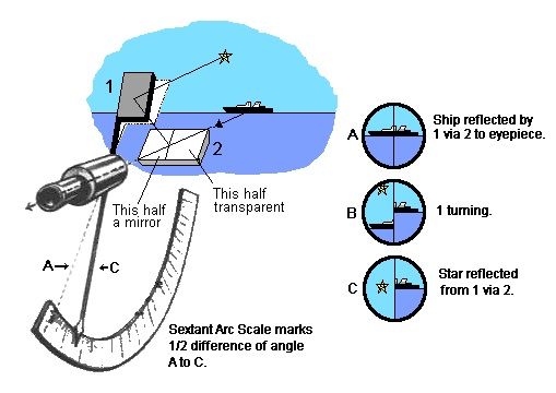
- When a ray of light is reflected by a plane mirror, the angle of incidence is equal to the angle of reflection, with the incident ray, reflected ray and the normal lying in the same plane.
- When an array of light, suffers two successive reflections in the same plane, by two plane mirrors, the angle between the incident ray and the final reflected ray is twice the angle between the mirrors.

Double Reflectivity depends upon the principle that the angle of incidence of a ray of light equals its angle of reflection (angles 1, and 2 in blue above when the mirrors are parallel). When the mirror is rotated away from the parallel, the total change in the angle of reflection from the rotated mirror is twice the amount of rotation (angles 5 and 6). If a body is 70 degrees above the horizon one of the parallel mirrors must be displaced by 35 degrees in order to send its reflected light rays through the peephole.
Marine Sextant
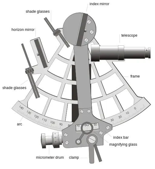
The sextant basically consists of a telescope, a half-silvered horizontal mirror which the telescope “looks” through and a moving arm on which the index mirror is fixed. By manipulating this arm a star or other celestial body can be made to appear on the horizon. Accurate adjustments are made by means of a micrometer knob. The angle can then be read off the arc and micrometer. The shades are to use when the object being looked at is bright – such as the sun.
Using Sextant
To use the sextant the telescope must be focused on the horizon. The celestial body to be observed, found and the sextant aimed at it. Bring the body down to the horizon by moving the arm along the arc and then clamp the arm. Using the micrometer knob make small adjustments while gently swaying the instrument slightly from side to side until the heavenly body just brushes the horizon.
When this is achieved instantly make a note of the time, seconds first, then minutes and hours, then the name of the body and its observed altitude. Every second of time counts – an error of 4 seconds equates to an error of a nautical mile in the position.
Errors of Sextant
Adjustable Errors
- The error of perpendicularity: is produced by the index glass not being perpendicular to the plane of the instrument. To check for this error, clamp the index bar at about the middle of the arc, and holding the sextant horizontally, with the arc away from you, look obliquely into the index mirror, are seen simultaneously. If they appear in alignment, the error of perpendicularity is not present. If not, turn the first adjustment screw at the back of the index glass, until they appear in alignment.
- Side Error: is caused by the horizon glass not being perpendicular to the plane of the instrument. To check for side error, by day, clamp the index bar at zero, hold the sextant horizontally and observe the horizon through the telescope. If the true horizon and its reflection in the mirror half of the horizon glass, appear in alignment, side error is not present. If they do not, side error exists. It can be removed by turning the second adjustment screw until the true and reflected horizons appear on the same line
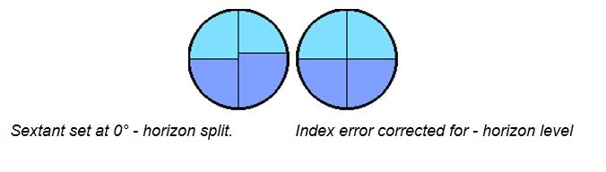
- Index Error: is caused by the index glass and the horizon glass not being parallel to each other, when the index bar is at zero. To find the index error, by day, using the horizon, clamp the index bar at zero and holding the sextant vertically, view the horizon through the telescope, if the true horizon and its refection appear in the same line, index error is not present. If they appear displaced vertically, turn the micrometre drum till they are in the same line. The micrometre reading then is the index error, which is on the arc if the micrometre reading is more than zero, and off the arc if it is less than zero. To eliminate index error, clamp the index bar at zero and looking through the telescope, turn the third adjustment Screw, till the true horizon and its reflection appear in alignment. The third adjustment screw is located below the 2nd adjustment screw, and towards the side, at the back of the back of the horizon glass.

- The error of collimation is due to the axis of the telescope not being parallel to the plane of the instrument.
Non-Adjustable Errors
- Graduation error is due to the inaccurate graduation of the main scale on or of the micrometre/vernier. (NonAdjustable Error).
- Shade Error is due to the two surfaces of the coloured shades not being exactly parallel to each other.
- Centring Error: is caused due to the pivot of the index bar not being, coincident with the centre of the circle of which the arc is a part.
- Optical errors: may be caused by prismatic errors of the mirrors or aberrations in the telescope lenses.
- Wear on the rack and worm, which forms the micrometre movement, would cause a backlash, leading to inconsistent errors.
This website was… how do you say it? Relevant!! Finally I’ve found something which helped me. Cheers!
very helpful for my research