
Gyro Compass is a navigational compass containing gyroscope motor that registers the direction of true north along the surface of the earth and it does not depend on magnetism.
or
A compass with a motorized gyroscope whose angular momemtum interacts with the force produced by the earth’s rotation to maintain a north-south orientation of the gyroscopic spin axis, therby providing a stable directional reference.
The Principle of Gyroscope
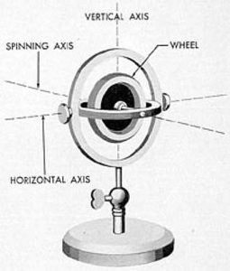
A gyroscope consists of a spinning wheel or rotor contained within gimbals which permit movement about three mutually perpendicular axes, known as the horizontal axis, the vertical axis, and the spin axis. When spun rapidly, assuming that friction is not considered, the gyroscope develops gyroscopic inertia, tending to remain spinning in the same plane indefinitely. The amount of gyroscopic inertia depends on the angular velocity, mass, and radius of the wheel or rotor.
PC: ed-thelen.org
Gyro Compass Basic Axis
If a gyroscope is placed at the equator with its spin axis pointing east-west, as the earth turns on its axis, gyroscopic inertia will tend to keep the plane of rotation constant. To the observer, it is the gyroscope which is seen to rotate, not the earth. This effect is called the horizontal earth rate and is maximum at the equator and zero at the poles. At points between, it is equal to the cosine of the latitude.
If the gyro is placed at a geographic pole with its spin axis horizontal, it will appear to rotate about its vertical axis. This is the vertical earth rate. At all points between the equator and the poles, the gyro appears to turn partly about its horizontal and partly about its vertical axis, being affected by both horizontal and vertical earth rates. In order to visualize these effects, remember that the gyro, at whatever latitude it is placed, is remaining aligned in space while the earth moves beneath it.
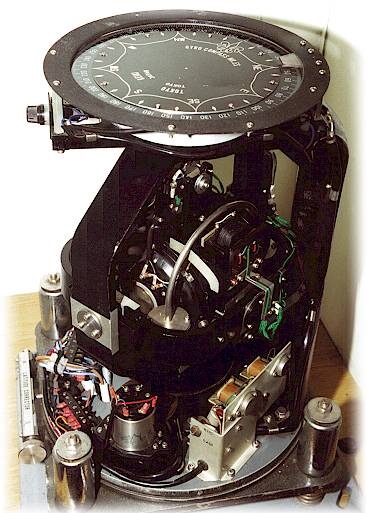
Cut Section of a Gyro compass
Gyrocompass Operation
The gyrocompass depends upon four natural phenomena:
PC: ed-thelen.org
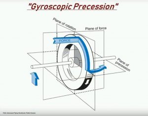
Gyroscopic Precession
- gyroscopic inertia,
- precession,
- earth’s rotation, and
- gravity.
To make a gyroscope into a gyrocompass, the wheel or rotor is mounted in a sphere, called the gyrosphere, and the sphere is then supported in a vertical ring. The whole assembly is mounted on a base called the phantom. The gyroscope in a gyrocompass can be pendulous or non-pendulous, according to design. The rotor may weigh as little as half a kilogram to over 25 kg.
To make it seek and maintain true north, three things are necessary.
- First, the gyro must be made to stay on the plane of the meridian.
- Second, it must be made to remain horizontal.
- Third, it must stay in this position once it reaches it regardless of what the vessel on which it is mounted does or where it goes on the earth.
To make it seek the meridian, a weight is added to the bottom of the vertical ring, causing it to swing on its vertical axis, and thus seek to align itself horizontally. It will tend to oscillate, so a second weight is added to the side of the sphere in which the rotor is contained, which dampens the oscillations until the gyro stays on the meridian. With these two weights, the only possible position of equilibrium is on the meridian with its spin axis horizontal.
To make the gyro seek north, a system of reservoirs filled with mercury, known as mercury ballistics, is used to apply a force against the spin axis. The ballistics, usually four in number, are placed so that their centers of gravity exactly coincide with the center of gravity of the gyroscope. Precession then causes the spin axis to trace an ellipse, one ellipse taking about 84 minutes to complete. (This is the period of oscillation of a pendulum with an arm equal to the radius of the earth.) To dampen this oscillation, the force is applied, not in the vertical plane, but slightly to the east of the vertical plane. This causes the spin axis to trace a spiral instead of an ellipse and eventually settle on the meridian pointing north.
Using the Gyrocompass
Since a gyrocompass is not influenced by magnetism, it is not subject to variation or deviation. Any error is constant and equal around the horizon, and can often be reduced to less than one degree, thus effectively eliminating it altogether. Unlike a magnetic compass, it can output a signal to repeaters spaced around the vessel at critical positions.
But it also requires a constant source of stable electrical power, and if power is lost, it requires several hours to settle on the meridian again before it can be used. This period can be reduced by aligning the compass with the meridian before turning on the power.
The directive force of a gyrocompass depends on the amount of precession to which it is subject, which in turn is dependent on latitude. Thus the directive force is maximum at the equator and decreases to zero at the poles. Vessels operating in high latitudes must construct error curves based on latitudes because the errors at high latitudes eventually overcome the ability of the compass to correct them.
The gyrocompass is typically located on the wheelhouse as close as possible to the center of roll, pitch and yaw of the ship, thus minimizing errors caused by the ship’s motion.
Repeaters are located at convenient places throughout the ship, such as at the helm for steering, on the bridge wings for taking bearings, in after steering for emergency steering, and other places. The output can also be used to drive course recorders, autopilot systems, plotters, fire control systems, and stabilized radars. The repeaters should be checked regularly against the master to ensure they are all in alignment. The repeaters on the bridge wing used for taking bearings will likely be equipped with removable bearing circles and azimuth circles.
hi dear
i need information about working of gyrocompass in pdf format
Dear Sir ,,
We are One of The Best Leading Exporter & Supplier For Various Kind of Reusable Ship Electronics Navigation-Communication & Automation Control System / Machinery Equipments / Spare Parts , Which Obtained From The Largest Ship Breaking Yard Situated In Chittagong Of Bangladesh , We Offer To Export Navigation / Communications & Machinery Equipments / Spare Parts At Any Destination Of The World Very Low & Competitive Price
AFSAR AHMED :- OWNER
E-mail:- sairamaritimeservice@gmail.com
Cell Phone:- +8801629196680/01970196680
Eidgah Bou Bazar Halishahar Road
CHATTOGRAM -4224 BANGLADESH
This post provides a clear and concise explanation of how a gyro compass works, making complex concepts easy to understand. I appreciate the detailed insights into its operation and practical applications on ships. It’s fascinating to learn how critical this instrument is for navigation. Great read!
Great post! I really appreciated the detailed explanation of the basic principles and operation of gyro compasses. It’s fascinating how they enhance navigation accuracy on ships. The inclusion of real-world usage examples made the content even more relatable. Thanks for sharing this informative piece!
This post on gyro compasses is incredibly informative! I appreciate how you broke down the basic principles and explained the operation in such an accessible way. It’s fascinating to learn about their crucial role in navigation on ships. Thanks for sharing such valuable insights!
Great explanation of how gyro compasses work! I always found it fascinating how they maintain true north regardless of the ship’s movement. The section on their operation and benefits over magnetic compasses was particularly insightful. Thanks for sharing this valuable information!
This post provides a clear and comprehensive overview of gyro compasses! I appreciate the detailed explanation of the basic principles and operations, especially how it differs from magnetic compasses. The usage insights on ships are incredibly useful for anyone in maritime navigation. Thank you for sharing this valuable information!
Thanks for the informative post! I always wondered how gyro compasses worked on ships. The explanation of their basic principles and operational details made it much clearer for me. It’s fascinating to see how technology plays such a crucial role in navigation.
This is a great overview of gyro compasses! I appreciate the clear explanation of their basic principles and how they operate on ships. The insights into usage scenarios really help in understanding their importance in navigation. Looking forward to more posts like this!
This post was incredibly informative! I never fully understood how gyro compasses worked until now. The breakdown of the basic principles and their operation on ships was especially helpful. Thank you for explaining this complex topic in such an accessible way!
This post does a fantastic job breaking down the fundamental principles of gyro compasses! I appreciate the clear explanations of how they operate and their significance on ships. It’s fascinating to learn about the technology that helps navigate the vast oceans. Thank you for sharing such insightful content!
This post on gyro compasses is incredibly informative! I appreciate the clear explanations of the basic principles and operations. It’s fascinating to learn how these systems play such a crucial role in navigation on ships. The diagrams really helped reinforce my understanding as well. Thanks for sharing!
Great article! I found the explanation of how a gyro compass works really helpful, especially the details on its advantages over magnetic compasses. It’s fascinating to see how technology has advanced navigation on ships. Looking forward to more posts like this!
This blog post on gyro compasses provides a clear and insightful overview of how they work and their essential role in navigation at sea. I particularly appreciated the detailed explanation of the basic principles and operation. It’s fascinating how these instruments maintain true north regardless of the vessel’s movement. Great resource for anyone interested in maritime technology!
Great post! I found the explanation of the gyro compass operation fascinating. It’s impressive how it maintains its accuracy regardless of the ship’s movement. Understanding its principles really helps in appreciating the technology behind navigation at sea. Thanks for such informative content!
This blog post does a fantastic job of breaking down the complexities of gyro compasses! I appreciated the clear explanations of the basic principles and how it operates on ships. It’s fascinating to learn how these instruments play such a crucial role in navigation. Thanks for sharing this insightful information!
This post provides a clear and insightful explanation of how gyro compasses work and their importance in maritime navigation. I appreciated the detailed breakdown of the operating principles and practical usage on ships. It’s fascinating to see how technology has evolved to ensure safer and more accurate navigation at sea!
This is a really informative post! I appreciated the clear explanations of how a gyro compass works and its importance in navigation. It’s fascinating to see how technology has evolved to ensure safer and more precise maritime operations. Thank you for breaking down such a complex topic!
Great post! I found the explanation of how the gyro compass operates really insightful, especially the part about its advantages over magnetic compasses. It’s fascinating to see how such technology enhances navigation on ships. Thanks for breaking it down so clearly!
Great post! I found the explanation of the gyro compass’s principles and operations very clear and informative. It’s fascinating to see how this technology plays a crucial role in navigation. Looking forward to applying some of these insights in my own studies!