The arrangement of loading and discharge lines is collectively known as the Ship’s Cargo System. The first oil tankers to carry petroleum products in bulk were equipped with very simple pumping systems. For the most part, they had a single line which ran forward and aft from a midship pump-room, in which were housed two steam reciprocating pumps. One pump served the tanks forward of the pump-room, while the other dealt with the oil from the tanks aft of this pump-room. Some of the more simple types with their engines amidships provided pumps in the engine room to handle the cargo, or alternatively the mainline was extended the length of the machinery spaces to feed the pumps housed in a small pump-room just forward of the engine room. In both cases, these vessels were unsuitable for the carriage of low flash products.
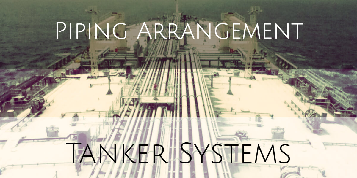
Piping Arrangement
The pipes leading from the cargo tanks to the pumps are termed as bottom lines, from the pump-room up to deck are called risers. The lines on deck are termed as deck lines. The lines which lead from the deck to the tanks are called drop lines. Besides these, there are Crude Oil washing lines on deck (COW lines). The COW main line usually branches off from the main discharge line in the pump-room. It further branches out to the various tanks on deck. There is also a small diameter line (Marpol line) which is used to discharge the last part of the cargo from the ship.
In the cargo tanks, the pipes terminate in a bellmouth. A tank may have two bellmouths – one main and one smaller stripper bellmouth. Alternatively, one bellmouth may serve the purpose of main as well as stripping discharge.
The piping system has evolved over the years to cater to varying cargo requirements. In a product tanker which is designed to carry many grades, we see that there are many more pipes so that many grades can be catered to. In a crude oil tanker, the piping is straightforward and simple.
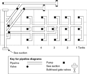
There are three basic types of pipeline systems:
- Direct Line system
- Ring main system
- Free flow system.
Each system has their uses and is designed to fulfill a need in a particular type of vessel.
Direct Line system
It consists of lines running longitudinally in the centre tanks and branching out to bellmouths in the centre and wing tanks. The system is uncomplicated and found on some crude carriers.
The advantages are that:
- it is easy to operate and less training of personnel is required
- as there are fewer valves, it takes less time to set up the valve system before commencing a cargo operation
- contamination is unlikely, as it is easy to isolate each section.
The disadvantages are that:
- the layout is not as versatile
- a very rigid system which makes it difficult to plan
Ring-main systems
It is also called the circular system. This type of piping system provides for the handling of several different types of oil. A particular tank can be pumped out either by a direct suction line or through another line by use of a cross-over. The system is very versatile.
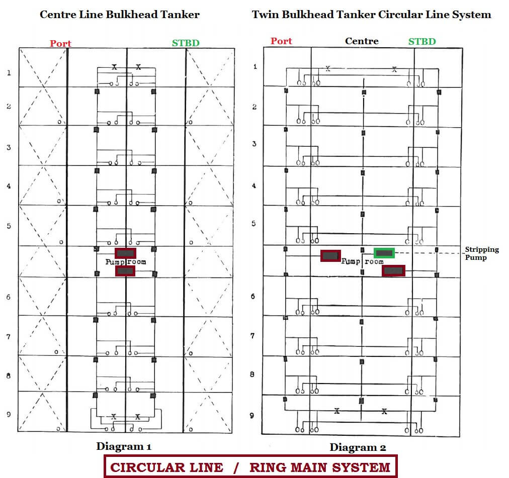
The pipeline system illustrated above in Diagram 1 is better suited to the centre line bulkhead type of ship. Each tank or oil compartment has two suctions — one Direct suction and one Indirect suction. The direct suctions for the port tanks are all on the port cargo line, and feed the port cargo pump. The indirect suctions for the port cargo tanks feed the starboard cargo line and the starboard cargo pump. Master valves are provided on each line between the tanks, so as to isolate each tank from the other when necessary. This particular vessel is not fitted with a stripping line and pump. This type of pumping system providing for the handling of several different types of oil was a natural development from the earlier types which were only suitable for one grade of oil. To drain the oil from the main tanks it was necessary to list first one way, and then the other, so as to keep the strum covered and to help the flow of oil towards the suction.
Diagram 2 shows a vessel fitted with a Circular Line or Ring Main but adjusted for the twin bulkhead type of vessel. This ship is also fitted with a stripping system. Inspection of the pipeline system shows that the pipeline travels around the ship in the wing tanks, crossing over from one side to the other. Each wing tank has a suction on the line which passes through it. The centre tanks have two suctions, one on either side leading to the port and starboard lines respectively. It will be noted that the master valves provide separation between the tanks as in the earlier system. When the level of the oil in any particular tank has fallen to a foot or less, the main pumps are switched to another full tank, and the stripping pump is brought into operation.
Free-flow system
In this system, the oil flows freely into the aft most tanks when the interconnecting gate valves are opened. Main suction bellmouths in a full free flow tanker will only be provided in the aft tanks. However, each tank is generally provided with a small stripping line. This system has the distinct advantage of having lesser and less complicated piping system in the tanks and is suitable for large tankers which usually do not carry many grades of oil. Obviously, the flexibility of operations is comparatively less as compared to other piping systems. Some ships are also designed as part free flow i.e. free flow system only between certain tanks, which is a hybrid or cross between a full free flow system and a ring main system.
Valves: The valves used in tankers for cargo can be either butterfly valves, gate valves or sometimes rarely even globe valves. At pump discharges, a non-return flap valve is usually fitted. A detailed description of the merits and demerits of each type of valve will be outside the scope of this course.
The valves may be hydraulically, pneumatically or manually operated. Manual valves can have an extended spindle to enable operation of a tank valve from the deck.
It is important to note that the valve closure period is deliberately slow to avoid surge pressures. In the hydraulic and pneumatic system, the timing is normally pre-set to a safe limit and rarely requires to be adjusted. However, in manually operated valves the closing time is regulated by the operator. Dangerous surge pressure can build up which can rupture a pipeline or a part of it even in a remote location. The higher the fluid pressure in the pipeline, the greater will be the risk of rupture and pollution. The most critical period is the last 25% when closing the valve or the first 25% when opening it. One can actually hear the liquid squeezing through the valve. The rate of closure during this period should be especially slow and controlled.
You may find below interesting:
I appreciate all of the diagrams you provided. This makes it much easier to understand and comprehend the purpose of the different systems. It is interesting to me that having a slow valve closure period helps to avoid surge pressures. I would have never thought of this solution, it’s pretty cool. Thank you for the detailed and interesting article!
Well presented