
General
An oil volume can only be measured at its prevailing temperature and it, therefore, follows that the standard volume must usually be calculated. Unfortunately, different countries have different standard (reference) temperatures.
Generally, the reference temperatures are:
- In Eastern Bloc, Brazil 20oC;
- In Western Europe 15oC;
- In the USA 60oF.
The situation is further confused in that there are primarily two volumetric units, which are:
- In metric countries the cubic meter (m )
- In non-metric countries the barrel (Bbl).
Combining a statement of volume with a statement of the reference temperature yields the following measurement systems
In Eastern Bloc, Brazil m3 at 20oC;
In Western Europe m3 at 15oC;
In the USA US Bbl at 60oF.
It is customary to refer to volumes at the reference temperature as Standard Volumes e.g US barrels @ 60oF or cubic meters @ 15oC.
However, confusion may arise in the latter case if the reference temperature is not stated (Bill of Lading and or Certificate of Quantity and or shore Quantity Calculations Certificate).
It should be noted that most crude oils are traded in Barrels.
GLOSSARY OF TERMS AND UNITS OF MEASUREMENT
Quantities
- On Board Quantity (OBQ) : All the oil, water, sludge and sediment in the cargo tanks and associated lines and pumps on a ship before loading commences.
- Quantity Remaining On Board (ROB) : All the measurable oil, water, sludge and sediment in the cargo tanks and associated lines & pumps on a ship after discharging a cargo has been completed, excluding vapour.
Sediment
Suspended sediment are non-hydrocarbon solids present in the oil but not in solution. Bottom sediment are non-hydrocarbon solids present in a tank as a separate layer at the bottom. Total sediment is the sum of suspended and the bottom sediment.
Water
Dissolved water: is the water contained within the oil forming a solution at the prevailing temperature. Suspended water is the water within the oil which is finely dispersed as small droplets
Note: It may over a period of time either collect as free water or become dissolved water depending on the conditions of the temperature and pressure prevailing. Free water is the water that exists in a separate layer,
Note: It typically lies beneath the oil. Total water is the sum of all the dissolved, suspended and free water in a cargo or parcel of oil.
Volumes
- Total Observed Volume (TOV) is the volume of oil including total water and total sediment measured at the oil temperature and pressure prevailing.
- Gross Observed Volume (GOV) is the volume of oil including dissolved water, suspended water and suspended sediment but excluding free water and bottom sediment, measured at the oil temperature and pressure prevailing.
- Gross Standard Volume (GSV) is the volume of oil including dissolved water, suspended water and suspended sediment but excluding free water and bottom sediment, calculated at standard condition e.g 15oC or 60oF and 1013.25 hPa.
- Net Observed Volume (NOV) is the volume of oil excluding total water and total sediment at the oil temperature & pressure prevailing.
- Net Standard Volume (NSV) is the volume of oil excluding total water and total sediment, calculated at standard conditions e.g 15oC or 60oF and 1013.25 hPa.
- Total Calculated Volume (TCV) is the gross standard volume plus the free water measured at the temperature & pressure prevailing.
- The Volume Correction Factor (VCF) is the factor depending on the oil type, density or its equivalent and temperature which corrects oil volumes to the Standard Reference Temperature (s). (ASTM Tables 54 A, B, C, D or 6 A, B)
Vessel Experience Factor
At the end of a ship loading or discharge operation, it is customary to compare the quantity loaded or discharged measured on shore with the quantity measured on board the ship. Both the shore figures & the ship figs will be subject to the effects of random errors and systematic errors so they are unlikely to agree exactly. The question is: “How closely should they agree?” In a perfect world, for any given vessel, a constant ratio between the ship’s figure & the shore figures should be achievable (even if the ship’s tanks are over or under-calibrated). In reality, this ratio is not constant but varies about a mean value which is known as the vessel’s experience factor. Such factors are often used at loading ports to provide a convenient means of checking the accuracy of B/L and ship’s figures. There is no reason why similar techniques cannot be used at the discharge ports, although in practice this is seldom done.
Institute of Petroleum (IP) Terminology:
1) Vessel Experience Factor (Loading) [VEFL]
The adjusted mean value of the Vessel Loading Ratio(VLR) obtained after several voyages.
2) Vessel Experience Factor (Discharging) [VEFD]
The adjusted mean value of the Vessel Discharge Ratio(VDR) obtained after several voyages.
The IP stipulates that the following types of voyages should not be used when calculating a VEF:
First voyage after dry-dock; Lightening operations; Voyages where the B/L has been based on shipboard measurement; Voyages prior to any structural modifications which have affected the vessel’s carrying capacity.
There is also a body of opinion which suggests that part cargoes (less than 80% of the capacity) should not be considered when calculating a VEF.
Units of Measurements
- Mass: Mass is a measure of the quantity of material in a body & constant, regardless of geographical location, altitude, atmospheric conditions or air buoyancy effects.
- Weight: Weight is accepted as being the value secured when an object is weighed in air. Now often referred to as ‘apparent mass’, and can be converted to mass by the application of an air buoyancy correction (Table 56 = weight correction for oils).
- Gross Weight In Air: Gross Weight in Air is the weight of oil including dissolved water, suspended water & suspended sediment but excluding free water & bottom sediment.
- Net Weight In Air: Net Weight in Air is the weight of oil excluding total water & total sediment.
- Density: The density is the ratio of the mass of a substance to its volume. (typically kg/m3 or sometimes kg/litre Since density is dependent on temperature & pressure these should be stated.
- Density @ 15oC (VACUO): Mass / Unit volume @ 15oC (typically kg/m3 or sometimes kg/litre)
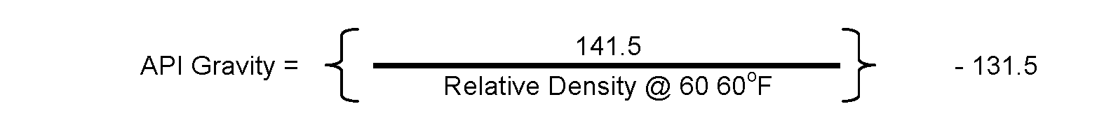
- Relative Density @ 60 60oF (Specific Gravity @ 60 60oF): The Relative Density @ 60 60oF is the density of a substance at 60oF to the density of pure water, also at 60oF = The Density of a substance @ 60oF ÷ The Density of pure water @ 60oF. Specific Gravity is now internationally known as Relative Density.
- API Gravity :

- Weight Conversion Factor (WCF): The Weight Conversion Factor is a factor dependent on the density, for converting volumes to weight in air. Such factors shall be obtained from the API-ISO-ASTM-IP Petroleum Measurement Tables (Tab56)
(All terms according to ISO or International Organisation for Standardisation)
Standard Tables
The 1980 / 1982 edition of the API-ASTM-IP Petroleum Measurement Tables for crude oils, refined products and lubricating oils (excluding light hydrocarbons, LPG’s and bitumen) are carried onboard according to the vessel’s trade.
Cargo Calculations in STASCO
Within Shell International Trading & Shipping Co. Ltd. Oil cargo calculations are based on:
- Metric System
- Standard Temperature / Pressure 15oC / 1013.5 hPa
- Weight in Air.
Explanations are given in the Charterer’s Instructions.
Oil quantity calculations should be made with the ASTM Petroleum Measurement Tables (ASTM Tables).
The equations are as follows:
- Volumes at 15oC on board a vessel always GROSS = Gross Volume at 15oC = Gross Standard Volume; Gross Standard Volume = Gross Standard Volume * Volume Correction Factor;
- Gross Weight In Vacuo (Mass) = Gross Standard Volume * Density @ 15oC (Vacuo). (Gross Weight in in Vacuo = GSV * Density @ 15oC (Vacuo)
Note: Hydrometers used on board are for density @ 15oC (vacuo).
The cargo statement requires weights in air to be recorded therefore the weight in Vacuo must be corrected for the buoyancy of air.
Gross Weight In Air = Gross Weight in Vacuo * Weight Correction Factor.
However, weight in vacuo is not normally calculated on board & therefore this part is normally omitted.
- Gross Weight In Air = Gross Standard Volume * Density @ 15oC (Vacuo) * WCF.
Note: Ship’s volume / weight quantities are always GROSS as vessels are unable to determine the:
- Dissolved Water;
- Suspended Water;
- Suspnded Sediment.
To compare ship’s figures loaded / discharged with shore figures always compare Gross Standard Volumes.
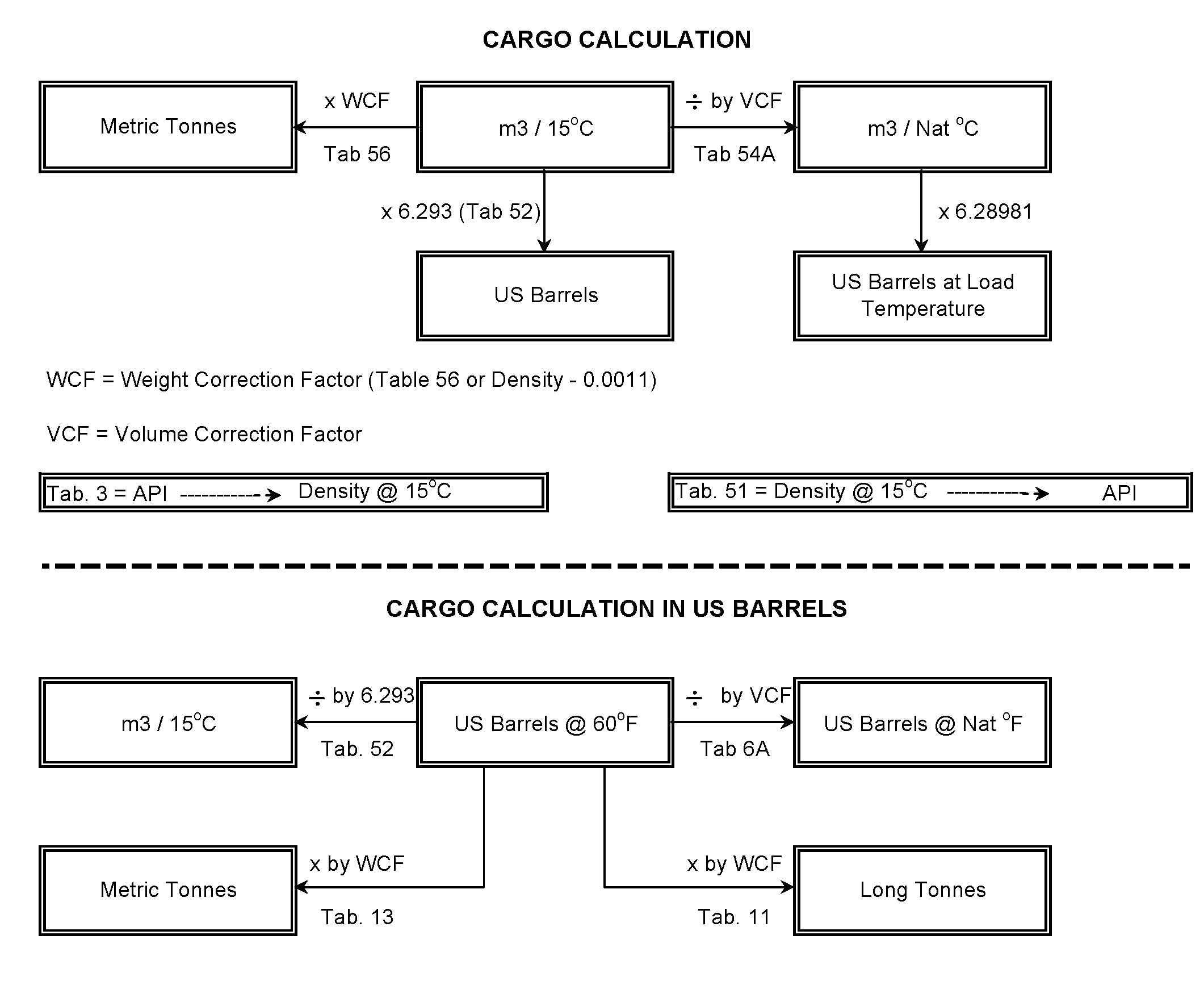
Manner of Calculations On Board
| Total obs volume in m3 at a temperature as observed by vessel Free Water m3 | – |
| Balance Volume m3 | |
| Bottom Sediment m3 | – |
| Balance Volume m3 Slops m3 | . |
| Gross Obs Volume in m3 at a temperature as observed by vessel Volume Correction Factor (ASTM Tables 54A, B, C, or D) | x |
| Gross Standard Volume in m3 at 15oC | |
| ASTM Tables 52 Factor | x |
| Gross Standard Volume in Bbls at 60oF. |
Note: ASTM Table 52 to be used for conversion of m3 at 15oC to Bbls at 60oF (As 15oC is not equal to 60oF).
| Gross Standard Volume in m3 at 15oC
Density @ 15oC (Vacuo) * Weight Correction Factor (ASTM Table 56). | x | |
| Gross Weight In Air in Metric Tonnes. |
Refer to the SONAR Operating instructions for more information on cargo calculation methods used by SONAR.
Ballast Calculations
Use the density of the water to find the WCF in ASTM Table 56.
Conversions in Weight
Use the ASTM Table Volume XI / XII. Note: Be aware of the fact that some terminals use weight in vacuo (e.g. Shell Netherlands Refinery BV; Pernis / Europort).
ASTM Tables Usage & Procedure of Calculations
| Series I – TABLE 5 & 6 – FOR API, OF, 60OF | |||
| Volume I: | Generalized Crude Oils (Tables 5A & 6A) | ||
| Volume II: | Generalized Products (Tables 5B and 6B) | ||
| Volume III: | Individual and Special Applications (Table 6C) | ||
| Series II – TABLE 23 & 24 – FOR RELATIVE DENSITY, oF, 60oF | |||
| Volume IV: | Generalized Crude Oils (Tables 23A & 24A) | ||
| Volume V: | Generalized Products (Tables 23B and 24B) | ||
| Volume VI: | Individual and Special Applications (Table 24C) | ||
| Series III – TABLE 53 & 54 – FOR KG/cm3 DENSITY, oC, 15oC | |||
| Volume VII: | Generalized Crude Oils (Tables 53A & 54A) | ||
| Volume VIII: | Generalized Products (Tables 53B and 54B) | ||
| Volume IX: | Individual and Special Applications (Table 54C) | ||
| Volume X: | Background, Documentation, Program Listings | ||
| Volume XI / XII – ASTM D 1250-80 – API standard 2540 and IP Designation 200 apply | |||
| Volume XI – ENTRY WITH API GRAVITY | |||
| Table 1 | Interrelation of Units of Measurement | ||
| Table 2 | Temperature Conversions | ||
| Table 3 | API Gravity at 60oF to Relative Density 60/60oF and to Density at 15oC | ||
| Table 4 | U.S. Gallons at 60F and Barrels at 60F to Litres at 15C against API Gravity at 60F | ||
| Table 8 | Pounds per US Gallon at 60F and US Gallons at 60F per pound against API Gravity at 60F | ||
| Table 9 | Short Tons per 1000 US Gallons at 60F and Barrel at 60F against API Gravity at 60F | ||
| Table 10 | US Gallons at 60F and Barrels at 60F per Short Ton against API Gravity at 60F | ||
| Table 11 | Long Tons per 1000 US Gallons at 60F and per Barrel at 60F against API Gravity at 60F | ||
| Table 12 | US Gallons at 60F and Barrels at 60F per Long Ton against API Gravity at 60F | ||
| Table 13 | Metric Tons per 1000 US Gallons at 60F and per Barrel at 60F against API Gravity at 60F | ||
| Table 14 | Cubic Metres at 15C per Short Ton and per Long Ton against API Gravity at 60F | ||
| Volume XII – ENTRY WITH RELATIVE DENSITY | |||
| Table 21 | Relative Density 60/60oF to API Gravity at 60oF and to Density at 15oC | ||
| Table 22 | US Gallons at 60F to Litres at 15C and Barrels at 60F to Cubic Metres at 15C | ||
| Table 26 | Pounds per US Gallon at 60F and US Gallons at 60F per Pound against Relative Density 60/60F | ||
| Table 27 | Short Tons per 1000 US Gallons at 60F and per Barrel at 60F against Relative Density 60/60F | ||
| Table 28 | US Gallons at 60F and Barrels at 60F per Short Ton against Relative Density 60/60F | ||
| Table 29 | Long Tons per 1000 US Gallons at 60F and per Barrel at 60F against Relative Density 60/60F | ||
| Table 30 | US Gallons at 60F and Barrels At 60F per Long Ton against Relative Density 60/60F | ||
| Table 31 | Cubic Metres at 15C per Short Ton and per Long Ton against Relative Density 60/60F | ||
| Table 33 | Specific Gravity Reduction to 60F for Liquefied Petroleum Gases and Natural Gasoline | ||
| Table 34 | Reduction of Volume to 60F against Specific Gravity 60/60F for Liquefied Petroleum Gases | ||
| Table 51 | Density at 15C to Relative Density 60/60F and to API Gravity at 60F | ||
| Table 52 | Barrels at 60F to Cubic Metres at 15C and Cubic Metres at 15C to Barrels at 60F | ||
| Table 56 | Kilograms per Litre at 15C and Litres at 15C per Metric Ton against Density at 15C | ||
| Table 57 | Short Tons and Long Tons per 1000 Litres at 15C against Density at 15C | ||
| Table 58 | US Gallons and Barrels per Metric Ton against Density at 15C | ||
| Volume XIII: | LUBRICATING OILS, TABLES 5D & 6D | ||
| Volume XIV: | LUBRICATING OILS, TABLES 53D & 54D | ||
| Please remember that normally the density or API is provided by the terminal or surveyor in the load ports and what is used will be dependent on the region/port of loading. For example in USA / Canada, Persian Gulf, API usage is prevalent, while entire of Europe and Asia use Density at 15C. However please ascertain, if Density at 15C is provided, whether it is in air or in vacuum. This is very important when finding out from Table 54, since the density provided there is in Air and hence same must be used. (Density at 15C in Air = Density at 15C in Vacuum – 0.0011 | |||
| PROCEDURE OF CALCULATIONS | |||
| Working with Density at 15oC in air: | |||
| 1) Observed Ullage – apply corrections – get Corrected Ullage | |||
| 2) Observed Interface – apply corrections – get Corrected Interface | |||
| 3) From Corrected Ullage, find Total Observed Volume TOV (in cubic metres) | |||
| 4) From Corrected Interface, find Volume of Water (in cubic metres) | |||
| 5) TOV – Water = Gross Observed Volume (GOV) of Cargo (in cubic metres) | |||
| 6) Use Density at 15C and Observed Temperature (oC) and find Volume Correction Factor (VCF) from Table 54 | |||
| 7) Gross Standard Volume (GSV) = GOV x VCF (cubic metres) | |||
| 8) Weight Correction Factor (WCF) = Density at 15C in vacuum – 0.0011 (or the Density at 15C in air) | |||
| 9) Weight in Air (Metric Ton) = GSV x WCF(Density at 15C in air) | |||
| 10) Weight in Vaccum (Metric Ton) = GSV x Density at 15C in vacuum | |||
| Working with API Gravity at 60oF : | |||
| 1) Observed Ullage – apply corrections – get Corrected Ullage | |||
| 2) Observed Interface – apply corrections – get Corrected Interface | |||
| 3) From Corrected Ullage, find Gross Observed Volume (in US Barrels) | |||
| 4) From Corrected Interface, find Volume of Water (in US Barrels) | |||
| 5) GOV – Water = Observed Volume of Cargo (in US Barrels) | |||
| 6) Use API Gravity at 60F and Observed Temperature (oF) and find Volume Correction Factor (VCF) from Table 6 | |||
| 7) Gross Standard Volume (GSV) = Observed Cargo Volume (Barrels) x VCF (in US Barrels) | |||
| 8) Find Weight Correction Factor (WCF) from Table 13 | |||
| 9) Weight in Air (Metric Tons) = GSV x WCF | |||
| Working with Relative Density at 60/60oF : | |||
| 1) Observed Ullage – apply corrections – get Corrected Ullage | |||
| 2) Observed Interface – apply corrections – get Corrected Interface | |||
| 3) From Corrected Ullage, find Gross Observed Volume (in cubic metres) | |||
| 4) From Corrected Interface, find Volume of Water (in cubic metres) | |||
| 5) GOV – Water = Observed Volume of Cargo (in cubic metres) | |||
| 6) Use Relative Density at 60/60F and Observed Temperature (oF) and find Volume Correction Factor (VCF) from Table 24 | |||
| 7) Gross Standard Volume (GSV) = Observed Cargo Volume (m3) x VCF (in m3) | |||
| 8) Weight in Air (Metric Ton) = GSV x Relative Density at 60/60F | |||
| Total observed volume (TOV) | |||
| The total volume of material measured in the tank including cargo (oil or chemical), free water (FW), entrained sediment and water (S&W), sediment and scale as measured at observed temperature and pressure. | |||
| Free water (FW) | |||
| Water layer existing as a separate phase in the tanks, normally detected by water-paste or interface detector and usually settled at the bottom of the cargo tank depending on relative density of the cargo. | |||
| Sediment & Water (S&W or BS&W) | |||
| Entrained material within the oil bulk, including solid particles and dispersed water, also sometimes known as base sediment and water (BS&W). Expressed always as a percentage of the total cargo quantity, is found out be collecting average sample of the cargo inline during transfer and calculated by centrifuge technique in a laboratory. | |||
| Gross observed volume (GOV) | |||
| It is the Total Observed Volume (TOV) less free water (FW) and bottom sediment, being the measured volume of product and sediment & water (S&W) at observed temperature and pressure. Bottom sediment are normally not present on board a chemical or clean oil product tanker and therefore not deducted whereas it may be present in a dirty oil carrier, but be very difficult to ascertain. | |||
| Gross standard volume (GSV) | |||
| It is the measured volume of product and S&W at standard conditions of 15°C and atmospheric pressure. In practice is the GSV the GOV multiplied by the volume correction factor (VCF) obtained from the appropriate ASTM/IP Petroleum Measurement Tables. | |||
| Net standard volume (NSV) | |||
| It is normally applicable only to Crude Oils. NSV is the GSV minus S&W, being a measurement of the dry oil quantity at standard conditions. For clean oil products and chemicals, the S&W is not normally included within the receiver’s quality specifications. | |||
| The term Weight in Air is that weight which a quantity of fluid appears to have when weighed in air against standard commercials weights so that each will have a mass (weight in vacuum) equal to the nominal mass associated with it. | |||
| The term Weight in Vacuum refers to the true mass of a fluid. | |||
| USE OF WEDGE FORMULA FOR OBQ / ROB CALCULATIONS & FREE WATER CALCULATIONS | |||
| The Wedge Formula is a mathematical mean being used to approximate the small quantities of liquid and solid cargo and free water on board prior to the vessel’s loading and after her discharge, based on the dimensions of the individual cargo tank and vessel’s trim. The Wedge Formula is to be used only when the oil liquid does not touch all bulkheads of the vessel’s cargo tank, that is to say the liquid oil lying in small pools among the bottom sediment. | |||
| In order to standarise the OBQ/ROB calculations on board the Crude Oil carrying tanker vessels, the following geometric form of the Wedge Formula shall be used and this form of the formula assumes that the cargo tank is ‘box shaped’ with no internal ‘deadwood’ or pipeline systems, heating coils etc. that would impact the accuracy of the volume calculated from the sounding. Furthermore this wedge formula calculation makes the enormous assumption that any ‘liquid’ found in a cargo tank is in the form of a regular wedge shape with its base at the aft bulkhead of the cargo tank. | |||
| It is obvious that such a series of assumptions normally can invalidate the absolute accuracy of the calculation immediately given, amongst other issues, the shape of the wing tanks (the turn of the bilge) and in particular those wing tanks at the fore and aft parts of the vessel. | |||
The calculation method for the Geometric edition of the Wedge Formula: | |||
| Assumption: Given the small angle involved with the trim of the vessel, then the ‘Sine’ of an angle can be considered as the same as the ‘Tangent’ (Tan) of an angle and consequently: | |||
| Step 1: | |||
| Correct the position of the sounding position with respect to the aft bulkhead of the cargo tank due to the trim of the vessel, distance = A | |||
| A = Tank Reference Height (Observed Height) x Tan X; | |||
| where X = the Trim angle of the vessel and; | |||
| Tan X = (Aft draft – Forward draft) / Length Between Perpendiculars (L.B.P.) of the vessel. | |||
| Step 2: | |||
| Determine the distance of the apex of the wedge from the aft bulkhead for obtaining information whether: | |||
| (1) should a Wedge Formula be used at all (kindly note that a wedge formula is not applicable if: (a) the liquid surface covers the total cargo tank bottom or the calculated apex of the wedge is at or beyond the forward bulkhead of the cargo tank or: (b) it is sludge ROB volumes only); | |||
| And | |||
| (2) whether the wedge is a regular wedge (which can be checked by comparison with alternative soundings being taken). | |||
| S = Observed Sounding; | |||
| F (Distance of the apex of the wedge from the sounding position) = S x Tan X; | |||
| E (Distance of the apex of the wedge to the aft bulkhead) = (F – A) + B; | |||
| where B is the distance on deck from the point of sounding to the aft bulkhead. | |||
| Step 3: | |||
| Determine the depth of the wedge at the aft bulkhead of the cargo tank, depth = D; D = E x Tan X | |||
| Step 4: | |||
| Knowing D (sounding depth at the aft bulkhead) and E (the distance from the aft bulkhead to the apex of the wedge), then the area of the longitudial cross section of the wedge may be calculated, | |||
| thus as the area of a triangle = (Base x Height) / 2 then; (D x E) / 2 = cross sectional area of wedge. | |||
| Step 5: | |||
| Having obtained the cross sectional area of the wedge, the volume of the wedge is calculated by multiplication by the breadth of the cargo tank (please note that the breadth of the cargo tank should be measured at the bottom of the tank at the aft bulkhead position and not at deck level or elsewhere within the cargo tank). | |||
| Volume of the Wedge = Cross sectional Area x Breadth of Tank | |||
| Throughout this calculation it is very important that all distances are in metres. Do not use centimetres for the observed sounding. | |||
| Alternatives: | |||
| Regardless above stated requirement, an I.S.O. standard method is also available in the event that any Cargo Inspector do not accept the geometric edition of the wedge formula. This method depends upon the accuracy of the vessel’s tank ullage calibration tables for the larger ullages / smaller soundings in the cargo tank. If the tank calibration tables are accurate for this region of the cargo tanks, then this method will give added accuracy to the general method of calculating tank residues after discharge. | |||
| This method is as follows: | |||
| Step 1: | |||
| Calculate DA (the Corrected liquid sounding at the aft bulkhead position); DA = D + {f(Y – (H x f))} | |||
| where: | |||
| D is the observed liquid sounding; | |||
| f is the Trim factor ( TS / LS ); | |||
| TS is the vessel’s trim; | |||
| Y is the distance of the sounding point to the aft bulkhead; | |||
| H is the reference height of the cargo tank; | |||
| LS is the vessel’s Length Between Perpendiculars. | |||
| Step 2: | |||
| Calculate Ct (the Tank constant); Ct = LS / ( 2 x TS x Lt ) (where Lt is the Length of the Cargo Tank). | |||
| Step 3: | |||
| Calculate the ‘k‘ coefficient; k = DA x Ct | |||
| if k > 0.5 wedge is not required to be carried out; | |||
| if k = 0.5 wedge must be carried out. | |||
| Step 4: | |||
| if k > 0.5 then calculate the volume of the liquid contained in the cargo tank from the calibration tables using the Observed sounding, D, applying the trim corrections. | |||
| Step 5: | |||
| if k = 0.5 then calculate DX (the wedge sounding). DX = DA / 2 | |||
| Step 6: | |||
| Enter the cargo tank calibration tables with DX, without applying trim corrections to equivalent volume VO. | |||
| Step 7: | |||
| Calculate the liquid wedge volume V1; V1 = VO x 2 x k | |||
| In addition to above methods it should be noted that if the procedures as specified in the vessel’s COW manual are being followed for the determination of the ‘Dryness’ of a cargo tank, namely, the sounding of the residues in four(4) differing locations within the cargo tank, then the foregoing methods of calculations can be avoided. | |||
| Assuming the shape of the individual cargo tanks is fairly regular / constant in a fore and aft direction and, notwithstanding the fact that the vessel will be significantly trimmed by the stern, then the four measurements, as suggested in the COW Manual guidelines, as obtained by sounding can be used to calculate an average sounding so as to obtain a single sounding. The single average sounding can be used directly in order to obtain an equivalent volume from the vessel’s tank ullage calibration tables | |||
| Such a method will provide a clearer indication as to the type and nature of the residues on the cargo tank floor as well as provide much clearer indications as to the profile of the residues within the cargo tanks. | |||
Calculation Credits: Nautraj Tanker Calculations
Would be very nice to get excel sheet to cargo calculations. There must be some awailable but from where to get it
You can find variety of cargo software for oil, LPG, LNG and chemicals on the website:
http://surveycalc.com/
Wow! This is very very educative as it explicitly explain what a cargo inspector should know.
HELPED A LOT, GREAT WORK
How to download the tables? Thanks a lot