
Anchors
The specific requirements for anchoring equipment in ships are laid down by the Classification Societies and is determined as per each ship’s displacement, her wind area down to the summer load line. These requirements are the weight of anchor, number of anchors, length of chain cable and breaking strength.
Requirements also specify that the cable must be secured in the chain locker by an arrangement whose breaking strength is greater than 15% and less than 30% of the tensile proof stress of the chain (Norske Veritas). Also, the breaker of the windlass must be able to withstand a pull of 45% of the tensile proof stress of the chain.
The following anchor equipment data for three ship types:
| EQUIPMENT | SUPERTANKER 330,000 DWT | CONTAINER VESSEL 40,000 DWT | PRODUCT TANKER 12,000 DWT |
| Anchor Weight | 23.0 tonnes | 9.90 tonnes | 4.65 tonnes |
| Chain Length | 770 mtr | 670 mtr | 570 mtr |
| Chain Weight | 286 kg/mtr | 128 kg/mtr | 57 kg/mtr |
| Chain Diameter | 177 mm | 78 mm | 52 mm |
| Chain Breaking Strength | 948 tonnes | 459 tonnes | 215 tonnes |
| Breaking Strength Shackle in Chain Locker | 145 tonnes | 92 tonnes | 60 tonnes |
Anchor Winch | |||
| Braking Power | 550 tonnes | 209 tonnes | 107 tonnes |
| Normal Lifting power | 100 tonnes | 40 tonnes | 20 tonnes |
| Max Lifting power | 115 tonnes | 48.5 tonnes | 22 tonnes |
| Medium Lifting Speed | 12 m/min | 12 m/min | 12 m/min |
| Max Lifting Speed | 12 m/min | 12 m/min | 12 m/min |
| Max. Holding Power | 110 | 48.5 | 22 |
| Anchor Hawse Pipe over waterline | 6.5 mtr | 11.7 mtr | 3.0 mtr |
The dimensions and breaking load of an anchor and chain have to be carefully matched such that the anchor does not break out of the soil until it experiences a load which is quite close to the chain’s breaking load. However, it is important that the anchor does, in fact, break out at that load or there is a risk of losing the anchor. The anchor’s holding strength is proportional to the anchor weight and is also a function of its design.
The most important variable in holding strength is, of course, the seabed conditions and the amount of ground cable laid out.
Experiments have shown that normal ship’s anchors have a holding power constant in the clay of 7-15, in the sand of 4.-8, and in mud 2-4. This constant holds good provided the pull on the anchor, transmitted through the chain, is horizontal at the anchor. In other types of seabed, the holding-power is different. In clay, somewhat greater than in rocky bottom. Some high holding power anchors as are commonly used in the offshore oil business have significantly greater holding powers than mentioned above.
If the chain makes an angle with the anchor of 5 °, the holding power of the anchor is reduced by approximately 25%. If this angle is increased to 15 °, the holding power is reduced by approximately 50%. To ensure a horizontal pull at the anchor, length of the chain deployed must be at least 5 times the distance from the hawse-pipe to the seabed. In unstable weather conditions, the length of chain deployed should be even longer.
During anchoring the ship’s speed over the ground must be very slow. How slow depends on the ship’s size but for most ships, there is a reasonable margin of error. However, in case of large tankers, the speed must be so slow that in certain conditions (e. g. in an unknown current) speed may be difficult to estimate. Taking the case of a fully loaded large tanker making 1 to 2 knots over the ground.
After the anchor is let go and the necessary scope of the chain is paid out, the windlass brake is applied. It is possible that the holding power of the anchor is greater than that of the brake and the brake will then slip. It follows that if ship’s speed is to be braked by use of the anchor alone, all the kinetic energy in the ship must be transferred to the brake of the windlass which may cause devastatingly high temperature at the windlass brake.
The safest way to anchor large ships is to motor the anchor out on the windlass. If the ship’s speed is 1-2 knots when the anchor takes the bottom nothing much will happen, the holding power being low as long as the cable’s length is short. It is now possible to estimate the ship’s motion over the ground by watching the chain and adjusting it accordingly. The cable is then laid out continuously in a controlled manner, with the chain being held under tension.
The magnitude of this tension may be estimated by watching the chain and may be regulated by manoeuvring the ship with propeller and rudder. When the desired length of cable has been laid out it may be ascertained that the anchor holds, by watching the chain. The chain must be stacked after having been tensioned and then watched to see that the anchor and chain take up the weight of the ship again thus proving it is holding. At this time the brake is applied to the chain and the chain stoppers are put in.
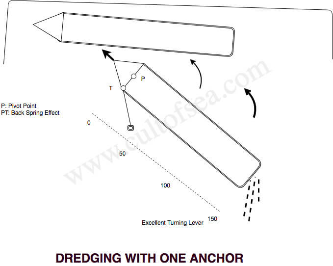
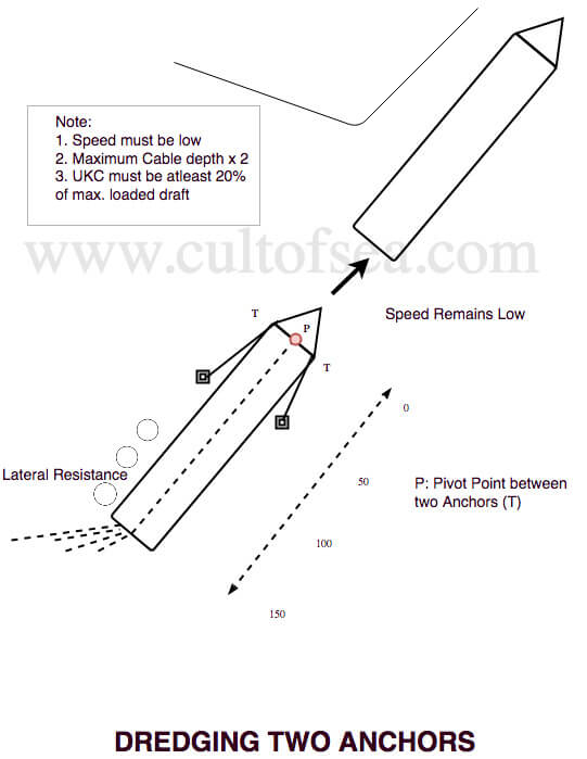
When manoeuvring close to a quay, the use of anchors is an effective means of controlling the movements of the stem, especially if there is a noticeable effect from a beam wind. The length of anchor chain used should be sufficient to decrease the ship’s speed to zero at dead slow ahead, but still allowing the ship to make a little headway at slow ahead.
As a rule of thumb guide, select a length of cable of 1.5×D, where D is the distance from the hawse-pipe to the bottom.
Note: The optimum length of cable may differ depending on the nature of the bottom, the type of anchor and the engine power at dead slow ahead.
When the anchor is used during manoeuvres the chain must always be held taut and the speed must not be increased above about 1 knot, otherwise, the anchor will hop over the bottom and lose its holding-power. As mentioned above the ship must be able to make some headway at slow ahead and the speed must be reduced to zero at dead slow ahead. If the ship approaches the quay in this way, the speed may be adjusted by altering between dead slow and slow. The port anchor is, of course, used when going starboard side alongside.
VLCC Anchoring
VLCC masters should avoid anchoring whenever it is practical. If advised of a short delay awaiting pilot or berth, the ship should be slowed and the arrival timed to avoid anchoring (manoeuvring capabilities and weather conditions permitting).
When anchoring is to be undertaken, the master must formulate an alternative operating plan, discuss it with the pilot if one is aboard, and advise the vessel officers as to action that should be taken should the anchor fail.
In normal anchoring, the VLCC master must be absolutely certain that the vessel is stopped and is not making any speed over the ground when the anchor is lowered. On vessels not fitted with speed logs, bearings must be taken and ranges watched as necessary to check the vessel movement.
The VLCC master must not drop the anchor on the brake under-normal anchoring conditions. Instead, it must be walked out using the windlass motor-preferably at not
more than 10 metres per minute. The windlass must not be de-clutched until there is a suitable scope on the cable, the anchor is secured and de-clutching becomes necessary to operate the mooring winch.
When walking the anchor out, the action of the chain will quickly inculcate whether or not the vessel is moving over the bottom and if necessary the chain can be checked before the anchor can take hold and cause damage. The master must instruct the officer in charge to keep the chain and where it leads under close observation.
Leave a Reply