A ship at sea is subjected to a number of forces causing the structure to distort. Initially, these may be divided into two categories, as follows:
Static forces – Ship floating at rest in still water.
Two major forces acting:
- the weight of the ship acting vertically down
- buoyancy acting up
Dynamic forces – due to the motion of the ship and the sea the structural stresses, caused by the above forces, to which the ship structure is subjected may be categorized as:
- Longitudinal stresses (hogging and sagging)
- Transverse stresses (racking and the effects of water pressure)
- Local dynamic stresses (panting and pounding)
Other stresses are caused by dry-docking, local weights, and vibration.
LONGITUDINAL STRESSES
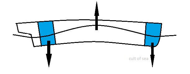
Hogging
Longitudinal bending stress would occur if the ship were subjected to local loading at the fore end and after ends, (e.g. ship with machinery aft and in light condition with ballasted fore peak tank) the hull would tend to ‘hog.’
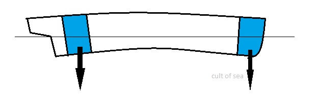
This effect would be made worse if the wave crest were amidships with wave length similar to ship length as shown.
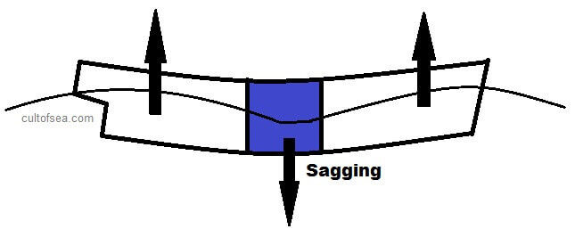
Sagging
If the load and the buoyancy distribution tended to distort the hull as shown (e.g.,. could be a ship with machinery amidships in light condition), is termed as sagging. This is made worse when the wave crests are at the ends of the ship, with a wavelength similar to ship length.
Longitudinal Stresses created by Hogging and Sagging can be very severe and can cause a ship to break up. The stresses are resisted by all continuous longitudinal material especially those parts further from the neutral axis. Double bottoms, i.e., centre girder, side girders, inner bottom and outer bottom longitudinals, keel and bottom shell, tank top plating. The side shell at the top (the Sheer strake) and deck stringer plates. As the decks, longitudinal girders and deck longitudinals also help resist the stresses, In tankers, longitudinal bulkheads also give great strength. Special steels for high-stress areas are now used, especially in large ships.

TRANSVERSE STRESSES
Racking
When a ship is rolling in a seaway or is struck by beam waves, the ship’s structure is liable to distort in a transverse direction as shown.
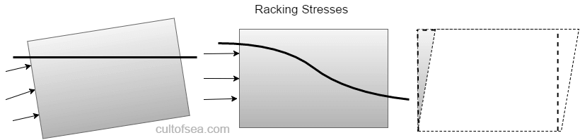
The stress mainly affects the corners of the ship, i.e., on the tank side brackets and the beam knees, which must be made strong enough to resist it. Transverse bulkheads, frames and web frames provide very great strength to resist racking.
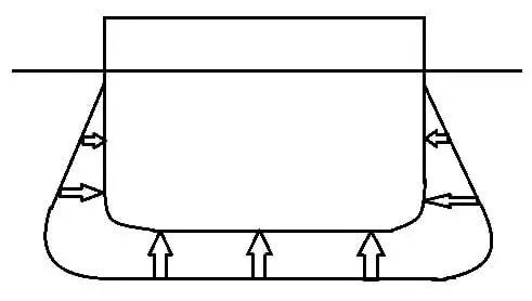
Water Pressure
Water pressure acts perpendicular to the shell of the ship, increasing with depth. The effect is to push the ship’s sides in and the bottom up. It is resisted by frames, bulkheads, floor and girders.
LOCAL DYNAMIC STRESSES
Panting
Panting is an in and out motion of the plating which occurs at the end of the vessel due to the variation in water pressure as the vessel pitches in a seaway. The effect is accentuated at the bow when making headway.

In general, the structure at the fore end is strengthened to resist panting to a distance of 0.15L aft of the FP. Forward of the collision bulkhead, ‘panting stringers’ are fitted not more than 2.0m apart. The stringers are bracketed to the shell frames, and panting beams are fitted on alternate frames under each panting stringer. Pillars are fitted on the centreline (usually a wash bulkhead) to tie the panting beams together. Deep plate floors are fitted on each frame station and are flanged on their upper edges. Between the collision bulkhead and 15%L aft of FP, intercostal stringers are fitted in line with the panting stringers.
Pounding
When a ship is pitching, the bows often lift clear of the water and then slam down heavily onto the sea, subjecting the forepart to severe pounding. TO compensate for this, the bottom is strengthened to 0.25L aft of F.P.
To resist pounding, the forward bottom structure is strengthened for between 25% and 30% of the length, depending on the ships Cb. Plate floors are fitted on each frame station (transverse framing) or alternate frame stations (longitudinal framing) with intercostal side girders not more than 2.2m apart. The four strakes of shell plating either side of the keel are generally increased in thickness in the pounding region.
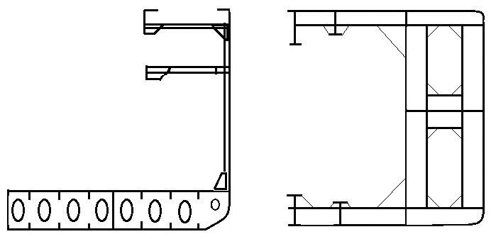
DRYDOCKING STRESSES
When the vessel is allowed to settle on the keel blocks before side blocks are positioned, transverse stresses will be induced in the structure, and it will have the tendency to sag at the bilges. These stresses are resisted by the double bottom structure (floors, etc.) transverse webs and bulkheads. Tankers having no double bottoms for most of the ship length have a deep centre girder with ‘docking brackets’.
Longitudinal stresses are created since the vessel generally grounds aft first and this creates longitudinal bending stress on the ship. Resistance to the stresses will be by all longitudinally continuous material, particularly those items furthest from the neutral axis. E.g., upper deck, bottom shell, and tank top together with associated longitudinals, girders, etc. (as for resistance to hogging and sagging)
High pressures are created aft as the vessel grounds aft first and this increases to a maximum as the water level drops and the vessel is about to take to the blocks along its full length. The ship structure is strongly constructed in this area as it is and the blocks in the docks are reinforced and tied together with steel ribbands.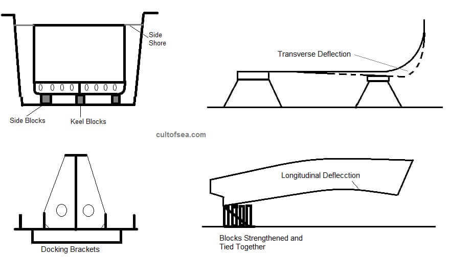
LOCALISED LOADING
Localised heavyweights, e.g. machinery or localized loading of heavy cargoes, e.g. ore may give rise to localised distortion of the structure.
The ends of superstructures may be major discontinuities in the ship’s structure giving rise to localized stresses which may result in cracking. Deck openings, holes cut in the deck plating, i.e. hatchways create areas of high local stress due to lack of continuity created by the opening. Other examples are stress set up by stays, shrouds, stresses set up in the vicinity of hawsepipes, windlass, and winches, etc.
Vibration from engines, propellers, etc. tends to cause stresses in the after part of the ship. These are resisted by extra stiffening in the double bottom under the machinery spaces in the region of the stern and afterpeak.
WHIPPING STRESSES
Impulsive forces that arise when severe pitching results in slamming (pounding) at the fore end cause the ship to vibrate at its natural frequency. These will be dampened along the ship length until coming to rest. High stresses can result from this action – referred to as ‘whipping stresses’.
This also occurs on container ships in adverse weather when pitching was not heavy. A frequency of about 50 cycles/min was produced which was near the 2-Node frequency. This potentially gives the worst vibration resonance possible. The resultant flexing of the hull could be observed along the line of the deck containers.
The normal method of detection is by longitudinal strain records. These show the whipping phenomena clearly superimposed on the normal ship movements, typically as follows:
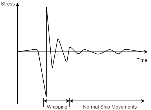
These stress reversal records show whipping characteristically by the higher than normal stresses that rapidly diminish. It has been found that reduced fore end flare will help reduce the magnitude of the impulse dies to pounding, thus reducing whipping stress.
All longitudinal, continuous material, especially that at some distance from the neutral axis will resist whipping. On some container ships, continuous hatch coamings and ‘strength’ bulwarks were fitted.
Strain Gauges: attached at a range of positions on the hull and strain is electrically measured from a Wheatstone Bridge connection. Stress is proportional to strain, and this stress can be determined.
Stress = Strain x E (Where E= 210 GN/m2 for steel)
These gauges can be fitted to critical points and connected to alarms to prevent excessive stresses occurring in heavy seas. Records can be built up over a period to provide future design statistics.
Torsion
Hybrid ship motions e.g., including roll, pitch, and yaw, together with wave effects, induce torsion in the hull. The torsional stresses produced are counteracted well by most ships since they are ‘box girder’ construction. However, ships having greatly reduced deck areas, (container ships are a good example), are more susceptible to torsional stress. Thus, the hull construction is a series of box girders, i.e. double skin on the sides and bottom.
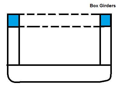
Further, specific box girder strengthening occurs along the hatch side together with continuous hatch coamings and strength bulwark. An extra row of containers may be stacked above the deck at side due to strengthening. At the hatch ends, transverse box sections connect the longitudinal box girders together forming a very rigid structure.
Do those have book references? I need some literature references for my research.
The information above is provided by handwritten notes though greatly inspired /learnt from “Ship Construction by D.J Eyres”.
Well understood
Dear All ,
can someone confirm if longitudinal stress calculations are to be carried out for all ships where Length is greater than 65 meter? And also where can i find this regulation? Thanks in advance!
Best Regards
Pol