The anchoring system is intended for safely mooring a vessel lying offshore in reasonable weather conditions. The system must be capable of keeping the vessel in position as per the holding power of anchor determined through the calculation of ‘Equipment Number‘. It is of paramount importance that the system is specified, designed, installed, operated and maintained in accordance with manufacturer’s instructions, Class requirements and the owner’s needs.
The holding power of the anchor determined from its EN (Equipment Number) will not be sufficient to maintain the position of the ship in severe environmental conditions. The original requirement for anchoring equipment, as laid down by the Classification Societies, were intended to provide equipment capable of holding the ship at anchor in sheltered and semi-sheltered waters in winds of up to gale force but did not consider the effects of the waves.
Typical Anchoring System
An anchoring system consists of the following:
| Type of Equipment | Components |
| Anchor | Crown, Shank, Flukes, Pins, Shackles and Swivel |
| Chain Cable | Links, Kenter shackles |
| Hawse Pipe | Bolster/hull reinforcement. Anchor/chain washing system. |
| Anchor Lashing | Wire/chain, shackles, bottle-screws, claws |
| Chain Stopper | Guillotine bar, locking pins |
| Windlass | Cable lifter, gears, clutches, bearings, brakes, stripper bar |
| Drive Unit / System | Power unit, controls, local controllers |
| Spurling Pipe | Spurling pipe sealing arrangements |
| Chain Locker | Cable self-stowing arrangements. Draining facility. Bitter end securing/release arrangement |
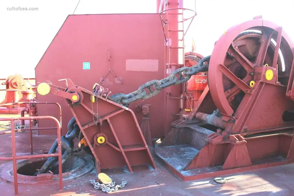
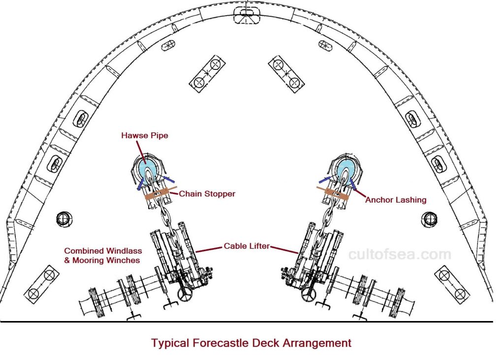
Basic Equipment Arrangement
The anchoring equipment is located on the forecastle, the most exposed place onboard. This requires an equipment design that is rugged but also ensures safe and relatively easy operation. Due to its exposed location, adherence to the equipment’s specified maintenance routines is important to ensure its ongoing operational capability. The majority of failures with the anchoring system can be traced back to the insufficient understanding of its capability and/or a lack of maintenance. [OCIMF]
Limitations of the Anchoring System
Typically, a windlass is required to heave in the weight of an anchor and chain from a depth of between 82.5 and 100 metres, depending on individual Class requirements.The windlass is not designed to break out the anchor from the seabed and may not be designed to lift chain lengths in excess of Class minimum requirements.
Mariners should be aware that windlasses are typically designed to lift a maximum weight of an anchor and three free-hanging shackles (shots) of cable.
The normal pulling force of the windlass is limited and in deeper water, it is usually not possible to lift the whole chain length with the anchor hanging free in the water. It should also be noted that existing Classification Society rules are based on anchoring in sheltered waters. While wind and current forces are considered, dynamic forces associated with waves and swell are not. As
anchorages are moved further offshore, these forces have increasing influence and they should be taken into account by owners when specifying equipment.
The weakest component in most anchoring systems is the windlass motor. The two main failure modes of motors are associated with heaving when there is too much weight on the cable and walking-out the cable with excessive way on the vessel.
When attempting to recover anchors in extreme conditions, the windlass will heave until its pulling force is exceeded by the tension in the chain. At that time, the windlass may start to render and such rendering may lead to damage to the motor’s components.This could result in catastrophic failure and the associated risk of Personal Injury.
When walking out the anchor by means of the windlass motor, it is important that the vessel’s speed over the ground is less than the walking-out speed, which is typically 9 metres/min, equivalent to less than 0.3 knots. Higher speeds over the ground may cause the motor to render.
Anchors
Ancient anchors consisted of large stones, basketfuls of stones, sacks filled with sand, or logs of wood loaded with lead; these held the vessel merely by their weight and by friction along the bottom. As ships became larger, they required a more effective device to hold them, and wooden hooks that dug into the sea bottom came into use as anchors. Iron replaced wood in their construction, and teeth or flukes were added to help the hooks dig into the bottom. Another major improvement was the addition of a stock or horizontal arm, that is set at right angles to the arms and flukes of the lower part of the anchor. The stock ensures that the arms rest vertically on the seabed, and thus one fluke will dig itself in, providing maximum holding power. This type, with its two flukes and its stock at right angles, remained the basic anchor for many centuries. It is known as a stock anchor.
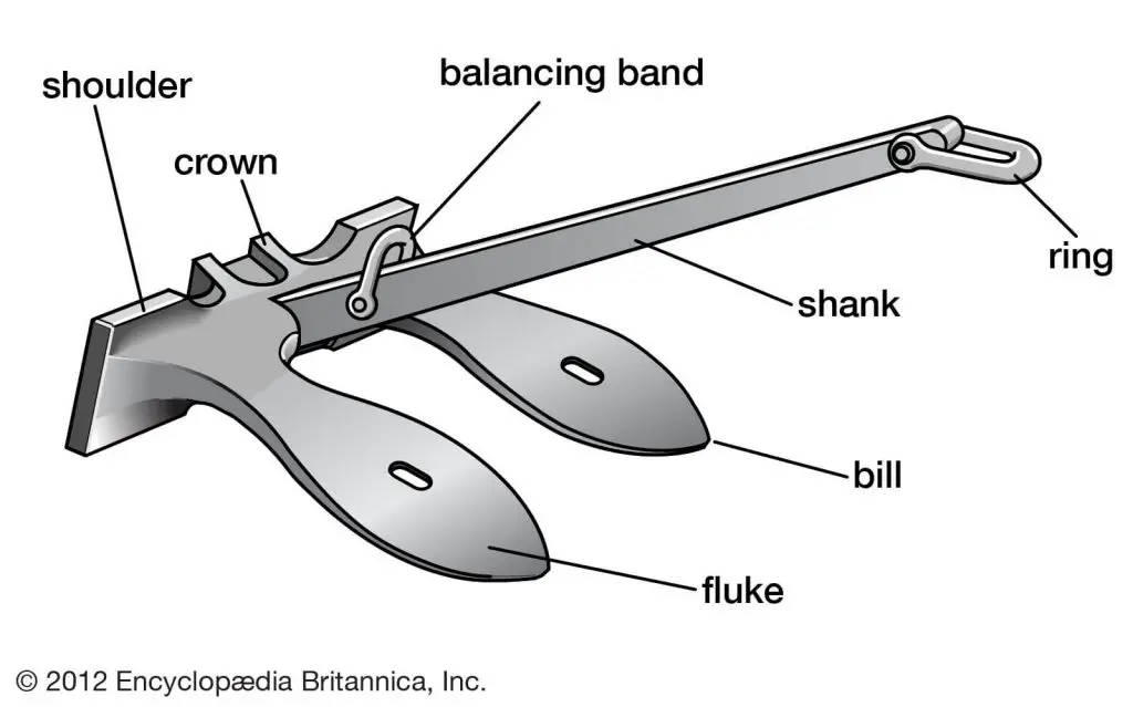
Curved arms began to replace straight arms in anchors early in the 19th century. This type of anchor, which is still used for light work and for boats is the Stock anchor. The ring (or shackle) is the part of the anchor where the chain or cable is attached. By removing the keep pin, the stock can be removed from the head so that the anchor can be stowed flat on an anchor bed in the ship. The stock must then be folded out again (i.e., stocked) before letting go, to ensure that one of the flukes digs into the ground. The vertical shaft of an anchor is called a shank; it contains a balancing band fitted at the anchor’s centre of gravity so that the anchor balances horizontally when lifted. The shank is joined to each arm at the crown. At the end of each arm is a fluke, which consists of a triangular flat face (i.e., a palm) with a pointed bill that digs into the ground.
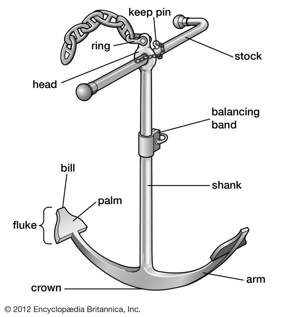
Stock Anchor, Source: Encyclopædia Britannica, Inc.
The stockless anchor, which was patented in England in 1821, came into wide use principally because of its ease of handling and stowing. The crown, arms, and flukes of a stockless anchor are cast in one piece and can pivot slightly from side to side on the shank. The flukes are long and heavy and have projecting shoulders at their base that catch on the seabed. As more drag is exerted, the shoulders force the flukes downward into the bottom. Stockless anchors have replaced the older stock anchor on most of the large ships of the world. To ensure a stockless anchor digs into the ground, the head is designed to pivot approximately 30-45 degrees either side of the shank. This pivot also enables the anchor flukes to lie flush against the ship’s side when the anchor is stowed in the hawse pipe.
Stockless Anchor, Source: Encyclopædia Britannica, Inc.
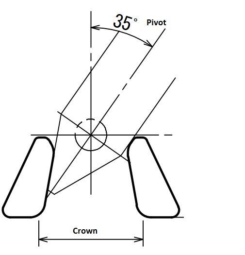
Stockless Anchor Pivot
Several other types of anchors are in common use. Lightweight, Danforth, and plow anchors have long, sharp flukes that pivot around a stock at the bottom of the shank and bury themselves deeply into the bottom; these anchors are generally used for yachts and other small craft. The mushroom anchor is shaped like an upside-down mushroom and is used widely as a permanent mooring for lightships, dredges, and lighters. [Encyclopædia Britannica, Inc.]
Chain Cable
A principal task of the chain cable is to provide enough weight to ensure that the anchor lies horizontally on the seabed so that it provides maximum holding force.
Anchor chain consists of 27.5-metre lengths of studded steel links, known as shackles or shots.When the chain is deployed and placed under tension, the studs prevent distortion of the links. Each shackle is connected to the other with a Kenter shackle, which consists of two interlocking halves that are connected by a locking pin.The Kenter shackles are slightly larger than the normal chain
links, are shaped to fit into the cable lifter and are normally identified by being painted or clamped.
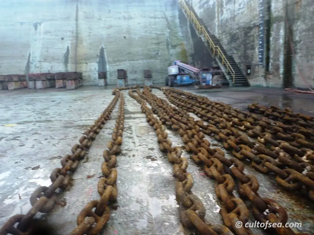
Anchor Chain Ranged
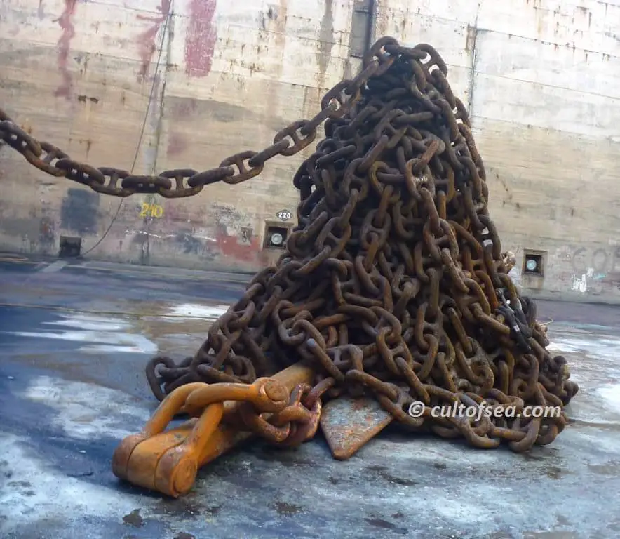
Anchor Chain Stacked
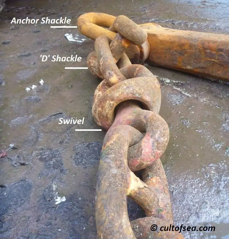
Anchor Chain Parts
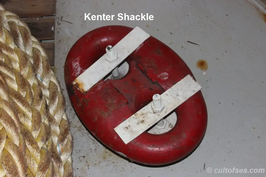
Kenter Shackle
Hawse Pipe
The main function of the hawse pipe is to guide the chain from deck level to outside the shell plating. The hawse pipe should be constructed to a size large enough to accommodate the smooth running of the chain and to provide secure stowage of the anchor, permitting it to drop freely when released without jamming or risking damage to the hull structure.
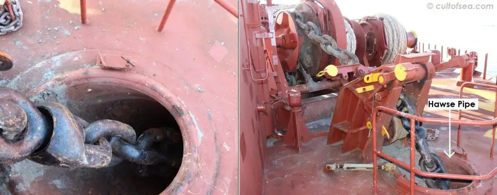
Hawse Pipe
Windlass Gears and Clutches
There are two types of windlass gears. For smaller chain sizes, the cable lifter is placed directly on the anchor winch main shaft and uses the winch gear only. The connection is made through a de-clutchable coupling or clutch.
For chain sizes above 50 mm diameter, the winch gearing is not sufficient and extra gearing is necessary. This is commonly in the form of a separate unit consisting of cable lifter, brake and gearing.The drive unit is normally a combined anchor and mooring winch.The drive shaft of the cable lifter unit is in line with the anchor winch main shaft and is connected through a coupling. In some arrangements mooring drums and/or warping ends may be installed on the extended drive shaft, in which case a clutching arrangement on the drive shaft is used to connect or disconnect the cable lifter from the winch.
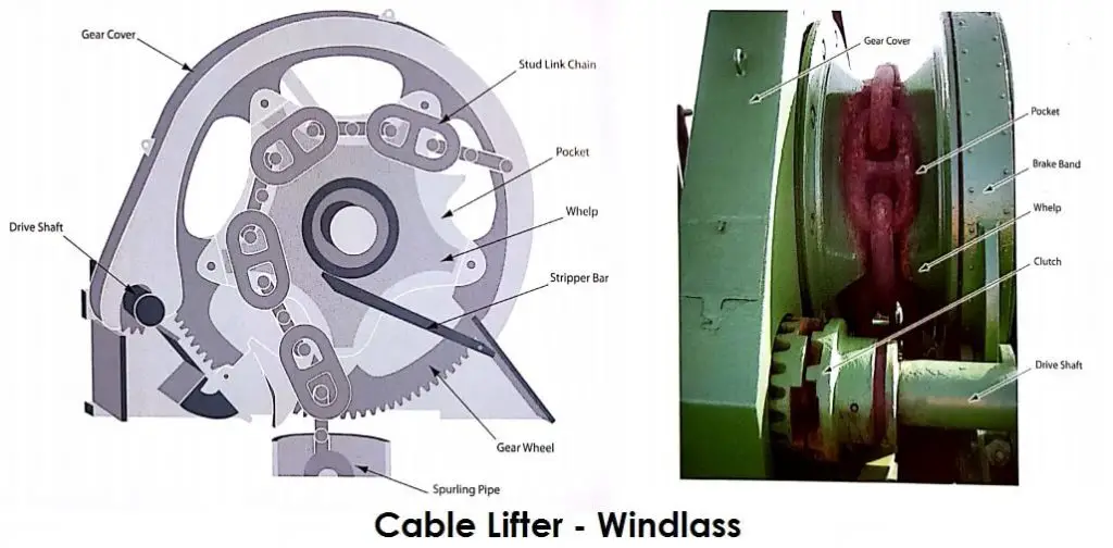
Source: ©OCIMF
Stripper Bar
The stripper bar consists of a steel bar connected to the cable lifter unit or directly to the deck and guided into the groove in the cable lifter.The function of the stripper bar is to break out the chain if it clings or sticks to the cable lifter above the spurting pipe during cable recovery.
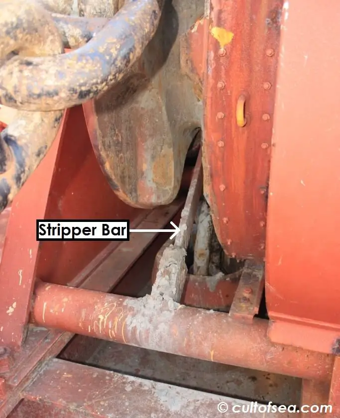
Stripper Bar
Chain Stopper
Two main reasons for installing a chain stopper:
- Acts as a guide for the chain into the hawse pipe.
- When Closed, transfer the chain forces into the ship’s structure.
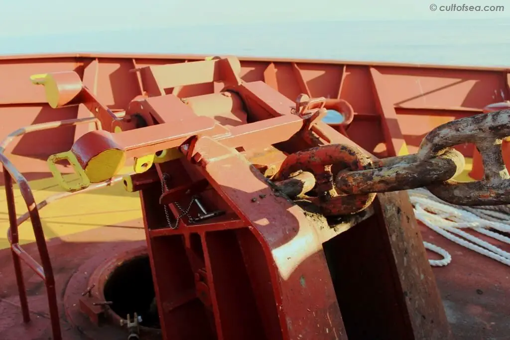
Chain Stopper
The design criteria specified by Class is to withstand a force equal to 80% of the Minimum Breaking Load (MBL) of the chain cable.
There are various types and designs of a chain stoppers, with the most common being roller stoppers of Guillotine type. The guide roller reduces friction and minimises the pulling force on the windlass. Other designs may be of the compressor type or may incorporate patent stopper arrangements. [OCIMF]
Anchor Lashing
The anchor lashing is used to tightly secure the anchor when in the stowed position. A loose anchor can cause damage to shell plating and in a worst-case situation could penetrate the hull. An anchor lashing can be arranged in different ways, although the most common is a wire or chain sling threaded through one of the chain links and secured via a bottlescrew to the deck structure or the chain stopper.
Another method is to use a claw, sometimes called a ‘devils claw, ‘ hooked on one chain link and tightened with a bottlescrew or alternative screw mechanism to the deck structure or the chain stopper.
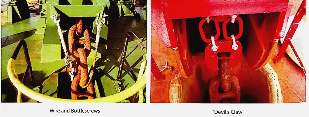
Anchor Lashing, Source © OCIMF
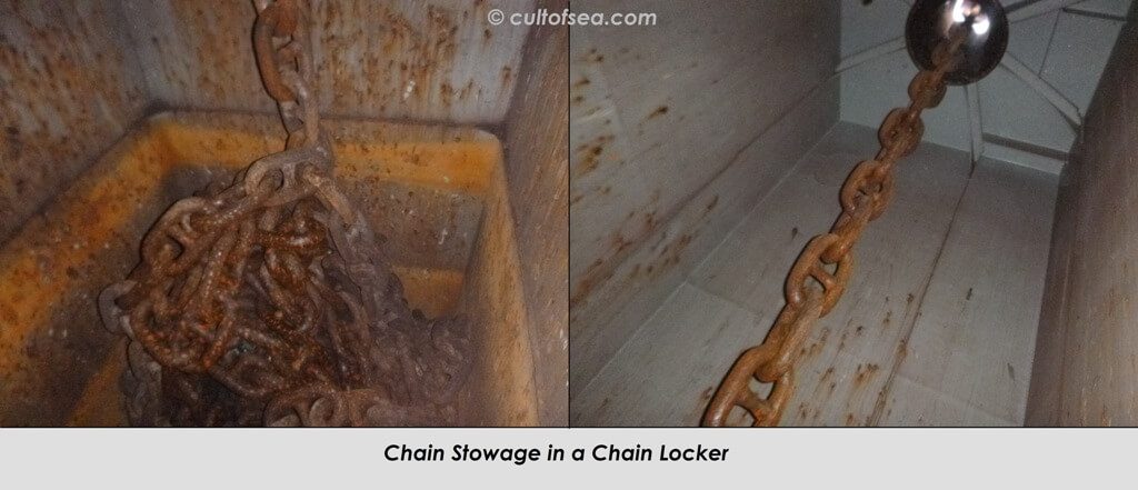
Spurling Pipe and Chain Locker
The chain locker provides storage for the chain cable and is situated under the deck with a pipe connection (Spurling pipe) to the anchor windlass. The Chain locker incorporates an arrangement to facilitate drainage, with the chain cable stowed on a grating.
The chain end (bitter end) is secured to the side or top structure of the chain locker by an arrangement that incorporates means for emergency release. It is recommended that this arrangement includes the facility for the chain to be slipped from outside the chain locker.
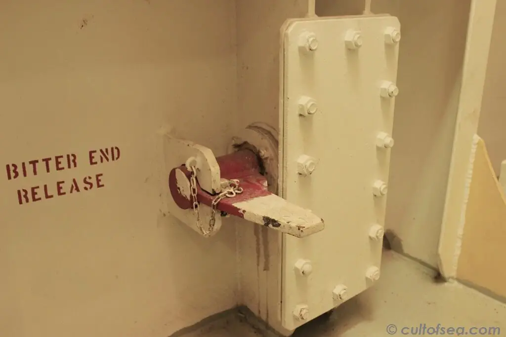
Bitter End
something is missing
Let us know, will be glad to add.!
the part where the anchor seats on the side of the hull
We have issue with Stbd windlass hydraulic motor assembly in our vessel LPG/C Unikum Spirit. Kindly give your contact details so that we can send the details of the motor and requisition
Is it a good practice or advisable to put the the CHAIN STOPPER when the cable is riding to the anchor? If this is so, and when the CHAIN STOPPER is jammed by the chain, in case of the emergency, the chain cable cannot be released by emergency method through the bitter end because the chain stopper is holding it.
What is the correct usage of the chain stopper?
Hello,
Lets clarify a few things first, I shall quote the Anchoring Systems and Procedures as per OCIMF guidelines; ” 4.7: Where a chain stopper is fitted, the brake capability of windlass must be at least 45% of the chain’s rule breaking load. If no chain stopper is fitted, then the brake capability must be increased to at least 80% of the chain’s Rule breaking load.”
Quote”
WHERE A CHAIN STOPPER IS FITTED, IT IS THE CHAIN STOPPER THAT IS DESIGN TO WITHSTAND THE DYNAMIC FORCES APPLIED TO THE CHAIN WHEN AT ANCHOR, NOT THE WINDLASS BRAKE.
unquote”
I understand that during emergency, chain stopper may get stuck and you may not release it from the bitter end, thats why we are advised to use windlass and eventually you will have to use engines to reduce load on the chain and pick up the anchor. I am stressing that use of chain stopper is must because it is designed to bear the load and not your winch brake system. Use engines to reduce the load and clear the chain stopper.
Does the chain stopper must be in position while anchor retrieved, i.e. stopper in between two links? As along with anchor chain wasted but not reach limit, say 12%, the chain stopper most probably can’t be put just between two links, is this a deficiency and must be rectified?
When the heavy swell, we dont care about M.B.L. % and other F.U.C.K.
We tight it as much as possible , because otherwise it will be slack and broke the chain stopper
As a student of ship design I’m interested to find out how I can find out the mass of anchor chain cable?
When were studs introduced to links in anchor chain?
Thank you for your time.
WE NEED TO THE CARRY OUT THE JOB OF ANCHOR STRIPPER BAR REPAIR
CAN YU ASSIST IN INDIA WHO CAN PERFORM THE JOB.
ATGTS Marine Services.
Why does the cable sometimes pile up in the chain locker and not fall into place? Sometimes have to open the chain locker access door and physically bang the chain in to place
Thanks for the information