
An instrument for measuring the speed of a ship through water is called a ship’s, or maritime, log. The same word is also applied to the daily record of a ship, though it is more properly termed a logbook.
History
In the years of sailing ships, the Dutchman’s log was an early method of calculating ship speed. An object that would float was thrown into the water near the forward part of a ship. In the after, or rear, section, a sailor with a sandglass noted the time taken for the ship to pass the object floating in the water. From the time and the known distance between the two points on the ship, a rough calculation was made of the ship’s speed.
The first really practical log was the chip log, a flat, quarter-circle piece of wood. A lead weight on the circular side of the piece, or chip, caused it to float upright and to resist towing. It was tossed overboard attached to a line having knots in it at known distances. The number of knots played out, correlated with a reading from a special sandglass, called a log glass, gave the ship’s speed. The term knot, meaning one nautical mile per hour, comes from the knots in the log line.
A later version was the patent log (towed log), which replaced the chip with a “fish” propeller-like rotator. The ships movement on the water turned the propeller and its revolutions were carried to a mechanical device called the “log register” and recorded, revealing the distance covered at any given time. The “Governor” was used to keep the rotation of the log line uniform and kink free. Sometimes the register electrically turned a repeater usually mounted on the bridge.
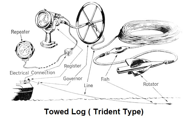
Towed Log / Patent Log
Other distance estimating methods
Tachometer
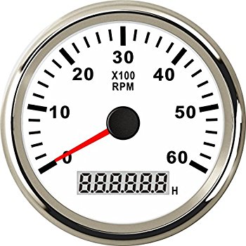
Tachometer
This is used for determining the revolution per minute (rpm) of a ship’s fixed pitch propeller. It is also used to determine the speed and distance travelled by ship. Knowing the pitch of the propeller (distance travelled in one revolution) and multiplying it by rpm, the speed of the ship can be determined and the engine distance covered can be worked out. However, the accuracy of this method is greatly affected by weather, by the displacement, trim or by the growth of seaweed or barnacles on the underwater portion of the ship’s plates.
The pitch is usually indicated in the ship’s particulars.
The Formula thus becomes
Engine Distance in Nautical Miles in 1 hour = (Average RPM in last 1 hour x 60 x Pitch in mm ) / (1853.207 x 1000)
Previous Observations
Distance estimation may be done by previously obtained observations also, e.g. If the vessel has been doing 12.5 knots from yesterday’s observed noon up-to-the last observed position at 0800 hrs today, then this speed may be taken and distance calculated for the period after 0800 hrs today to the present time today, provided that the weather condition and engine parameters remain same throughout.
Modern Logs
Pitot Log
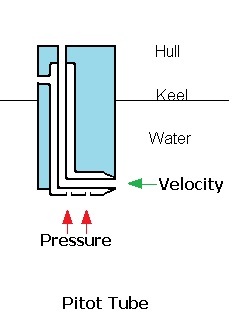
Pilot Tube
Pitot-static tube, which functions by sensing the difference between static and dynamic water pressures. Static pressure depends on the depth and density of the water, dynamic pressure is proportional to speed. Projecting through the bottom of the ship is a tube with a hole at its forward end to record the dynamic pressure and two other holes at right angles to record the static pressure. When the ship is motionless, the dynamic and static pressure are equal, when the ship moves, dynamic exceeds static. The difference varies as the square of the ship’s speed.
The Electromagnetic Log
This is based on the induction principle. A coil in the sensor protruding under the keel is supplied with an alternating current. The sensing electrodes on the outer side of the sensor measure the voltage difference generated in the surrounding water by induction due to the current in the coil and movement of the sensor with respect to the water. This voltage difference is proportional to the speed of the ship and thus indicated. The integrated values of the speed give the distance covered.
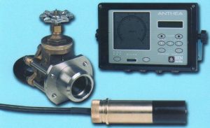
Electromagnetic Speed Log in either a simple or dual axis configuration with 2 line LCD display in an IP65 rated metal case, which displays Speed on a circular bar graph.
It operates on the principle of Doppler Frequency shift in the sound waves transmitted from the transducers fitted under the keel due to vessel speed.
Find below article for detailed study of Doppler Log.
i like the up date of marine vessel also wish to know more pratically of the maintenace of the inert gas system and maintenance operation
really appreciate your comment!