
One of the dangers faced by a ship is that of running aground. Usually, a vessel determines its position by means of GPS, Radar, Decca, Loran or visual bearings. The depth of water is checked from the echo sounder just as a matter of routine to see that the depth obtained matches with that show on the chart. However when the position is not accurately known while approaching the port, or crossing over a bar, or near the mouth of a river, or in a poorly surveyed area, the under-keel clearance and depth of water needs to be known. The echo sounder comes in handy in such situation.
An Echo Sounder is a type of SONAR (Sound Navigation And Ranging) device used to determine the depth of water by transmitting sound pulses into water
Principle
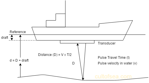
It works on the principle of transmitting sound waves from ship’s bottom and then measuring the time taken for the echo to be returned from sea. If the velocity of sound in water is known the time will be proportional to the distance travelled.
The time taken by the waves to travel to and from the seabed is measured and depth can be determined, by the formula Distance=Velocity x Time/2
Reason for using sound waves
For using the principle of ranging it is necessary to send some for energy signal and measure the time duration for its reflection to arrive. In case of echo sounder, the signal cannot be electromagnetic, as there is heavy attenuation in water. It cannot be light because water is not transparent and there is no mirror-like reflecting surface at the seabed. Sound propagation is by setting up vibrations in the medium. Water is virtually incompressible so if vibrations of very small magnitude are set up they can travel great distances.
Creation of sound waves
This can be done by two methods viz. magnetostriction and electrostriction.
Magnetostriction
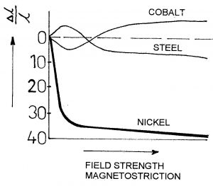
Ferromagnetic material such as iron, cobalt, nickel experience change in length when placed in a magnetic field. This occurs due to the rearranging of the domains or molecules within the material.
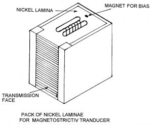
In case of iron and cobalt the change in length is expansion and then contraction but in case of nickel, it is the only contraction. Nickel is more commonly used, as its change per unit length is highest of all. The process is also reversible; meaning that if the length of such materials is changed it will create a magnetic field around itself. The change in length will take place even if the direction of the field is reversed. Therefore, if an alternating current is used to create the field then the frequency of nickel contraction will be double of that of the current. This handicap is overcome by using a permanent magnet to create a magnetic bias. The field created by the alternating current will either increase or decrease but it never changes direction. If bias field says 5 units and the current creates a field of 4 units then the results will vary between 1 and 9 units. Frequencies up to a few hundred kHz are therefore possible with magnetostriction.
Electrostriction
Crystals of certain materials like lead zirconate, lead titanate and barium titanate and quartz etc. experience potential between two faces when the crystal is stressed.
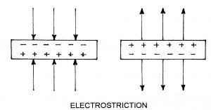
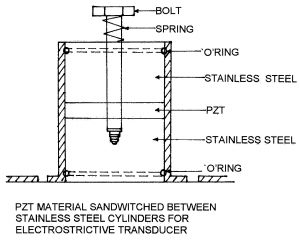
If a face gets a positive charge on compression, then it will get a negative charge if tensional force is applied. This property is also reversible i.e. if the potential is applied to two faces the crystal will experience tensional or compressive forces leading to change in dimension. For a given crystal the change in dimension is maximum along a particular axis. So while cutting a crystal care is to taken see that the faces selected will provide a maximum amplitude of vibration. The natural frequency of vibration will depend upon physical dimensions of the slice. For creating very high frequency a very thin slice is used. Frequencies up to 1 MHz are possible.
Working
The acoustic pulses of very short duration are transmitted vertically at the rate of 5 to 600 pulses per minute having a beam width of 12 to 25°. These pulses strike the seabed and get reflected back towards the receiving transducer as echoes. These received echoes are converted into electrical signals by the receiving transducer and after passing through the different stages of the receiver, the current is supplied to the stylus which bums out the coating of the thin layer of aluminium powder and produces a black mark on the paper indicating the depth of the seabed.
Errors of the Echo Sounder
- The velocity of propagation in water The velocity of acoustic wave changes if temperature, salinity or pressure changes and since velocity is not correct, the depth recorded will be inaccurate.
- Stylus speed error: The stylus is rotating with a certain constant speed and the speed of the stylus that the time is taken for the stylus to travel from top to bottom is exactly equal to that for an acoustic pulse to travel twice the distance of the range selected. Due to the fluctuation in the voltage, the speed of the stylus motor changes hence the depth recorded Will be inaccurate. It should be checked periodically and adjusted as per the instruction is given in the manual.
- Multipath Echoes: The echo may be reflected a number of times between the keel and the seabed, thereby giving multiple depth marks on the record, in such case the first echo is the correct depth.
- Pythagoras error: This error is found when two transducers are used one for transmission and other for reception.
- Thermal and Density layer. The density of the water varies with temperature and salinity, which will tend to form different layers. It is possible for echoes to return from the surface of these layers and a faint line appears between zero and actual depth.
- Zero line adjustment error If the zero adjustment is not correct, the depth recorded will not be correct.
What are an Echo Graph and Echometer?
Echo Graph
It consists of paper coated with aluminium or other good conductors, stylus, belt, conducting bar, sensors, actuator magnet, time delay unit and trigger unit. Paper may be graduated or a scale may be provided next to it. Calibration is in metres.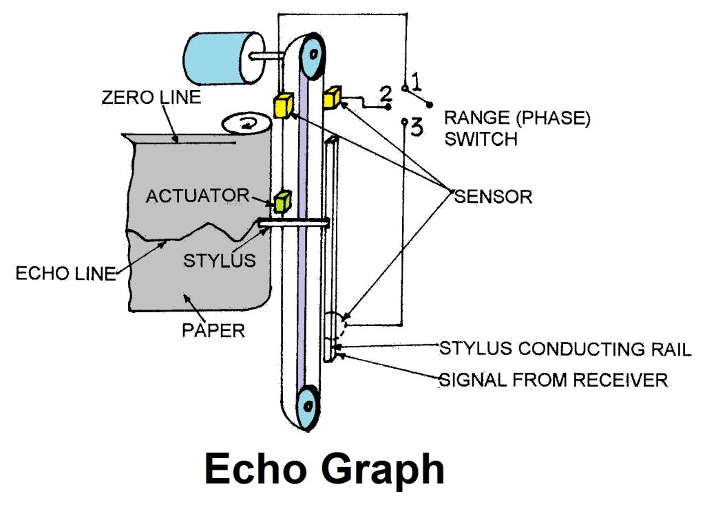
When the actuator magnet passes over the sensor, the sensor sends a signal to trigger unit. This activates transmitter after a time delay, which feeds high voltage signal to transducer for onward transmission of sound waves. The transmitter also sends a weak electrical impulse to stylus via the conducting rail. The stylus moves over a paper which is coated with electrically conductive material and which moves over a metal plate. The electrical impulse carried by stylus causes a layer of paper to be burned off making a mark on the paper. This mark coincides with the zero of graduation. The time delay is such that the mark on the paper is made to coincide with departure of sound wave from the transducer. When the echo returns the mechanical vibrations set up electrical signal, which is fed to the stylus. The stylus makes a second mark on the paper. The depth can be read from the graduation s on the paper or by help of a scale, which is next to the stylus. If echo were received after the stylus has gone past the paper area there would be no visible indication. In other words the movement of the stylus outside paper area will be unutilised. In order to put this to use more than one sensor is fitted. In the figure three sensors are shown. By selecting sensor No.2 the actuator will activate the transmitter before the stylus has reached the zero mark. The echo will be received while the stylus is on the paper. If at sensor No.1 the range is say 0-50 m. at sensor 2 it 50-100 and sensor 3 it is 100-150 m. Thus if the seabed is 75 m. from the keel the stylus will make a mark at halfway on the paper provided sensor 2 is in use. While using sensor s 2 or 3 there is no zero mark indication.
This method of increasing the range is called ‘phasing’ because the start of the pulse is not synchronised (not in phase) with the position of the stylus on zero line on the paper. Another way of increasing the range is by changing the speed of stylus. Suppose the speed of stylus is reduced to 1/4th then it will take four times the time to travel the length of the paper. With speed of sound remaining unchanged the paper will then represent a range of 0-200 (four times of 0-50), while on sensor 1, 200-400 on sensor 2 and 400-600 meters. on sensor 3.
The control switch, which changes the stylus speed, also changes the duration of pulse, pulse repetition rate (PRR) and the time delay for making the zero mark. Pulse will be longer, PRR will be smaller and time delay will be increased, as the stylus will take a longer time to reach the zero line. Echo meters usually use a combination of phasing as well as the change of stylus speed, to achieve a wide detection range and retain good resolution at short and medium ranges.
Echometer
This gives an analogue or digital readout of the soundings.
hi dear
i want to know about testing of transducer in ducking
I have a Ferrograph inshore echo sounder but without the 143kHz transducer. it is a valve/tube device working from the boats 24VDC supply. The display is the spinning type. i am going to need a transducer or make some kind of dummy load to test it but I have no details of impedance, power etc.
would you have a schematic by any chance or a service manual. it seems to be 1964 to 1969 vintage
Cheers
Martin
An echo sounder, also known as a sonar or depth sounder, uses sound wave reflection to determine the depth of water. This is how it works:
1. **Pulse Generation:** The echo sounder produces a brief burst of high-frequency sound waves, often in the ultrasonic range (above the human hearing range).
2. **Sound Wave Propagation:** These sound waves flow downward via the water.
3. **Reflection from the Seabed:** When sound waves collide with the seafloor or any underwater object, they are reflected back to the surface.
4. **Receiving the Echo:** The transducer (a specialized underwater microphone) on the echo sounder detects the returning sound waves.
5. **Time Interval Measurement:** The echo sounder measures the time it takes for the sound wave to travel.
An echo sounder, also known as a sonar or depth sounder, uses sound wave reflection to determine the depth of water. This is how it works:
1. **Pulse Generation:** The echo sounder produces a brief burst of high-frequency sound waves, often in the ultrasonic range (above the human hearing range).
2. **Sound Wave Propagation:** These sound waves flow downward via the water.
3. **Reflection from the Seabed:** When sound waves collide with the seafloor or any underwater object, they are reflected back to the surface.
4. Receiving the Echo: The transducer (a specialized underwater microphone) on the echo sounder detects the returning sound waves.
5. Time Interval Measurement:The echo sounder measures the time it takes for the sound wave to travel.
Echo-sounder is primary acoustic equipment used for navigation and for fish finding purposes. ➢It works on the principle of sound wave propagation in water. amplifier of transmitter before it reach to transducer. concentrate the sound energy which is emitted as a beam.
Errors of the Echo Sounder
The velocity of propagation in water The velocity of acoustic wave changes if temperature, salinity or pressure changes and since velocity is not correct, the depth recorded will be inaccurate.